Digital Pot with Arduino

Hi,
I am a newbie in electronics. Please correct me if I am wrong.
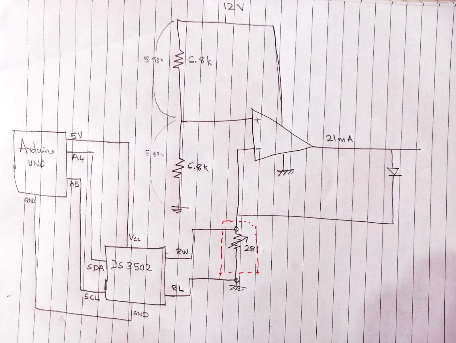
I am replacing a pot with a digital pot (DS3502) in a circuit.
The Vcc of the circuit is 12V. But the digital pot can have a maximum of 5.5V as Vcc.
I am controlling the digital pot with an Arduino UNO. Can I use 5V from the Arduino as the Vcc of the digital pot and 12V as the Vcc of the circuit?
I kept the ground common for both.

The connection is as below:
DS3502 Arduino Uno


VCC --- 5V
GND --- GND
SDA --- A4
SCL --- A5

DS3502 Circuit
RL --- GND
RW --- Circuit

This is a constant current circuit of 21mA, to drive a laser. But I want to slightly tune the intensity of laser using the digital pot. So I am replacing it with digital pot. My question is since the Vcc of circuit (12V) is different, will my digital pot work in circuit if connect 5V Vcc(from Arduino UNO) to it. For me, it is not working and showing as an open circuit :frowning:
I have only use RL and RW to circuit. RH is kept opened. Do I need to connect RH? I don't have much knowledge in circuits. Please spare me if I am wrong :wink:

Consult the datasheet: https://www.analog.com/media/en/technical-documentation/data-sheets/DS3502.pdf. As far as I can see, it's safe

Looks like you're missing a few connections :wink: I suggest that you provide a simple drawing (photo of paper/pencil is OK).

What is the circuit in which you want to replace the potentiometer?

Further I think that it's out of my league.

Well... Theoretically YES. (If you're using the Output of the Dev board to input to your device)
But i agree with @sterretje that

  • A Circuit diagram would be invaluable
  • There are a few things missing here as well (that would be solved with the diagram)

I reckon draw up a diagram or do the C.A.D. thing and take a picture of the project and upload both photos. Get as close up as you can on the project (Most people casually take a shot from way back which is rather useless)
this way we can help you better.

It looks as if the project would be feasible. We cant check any further without knowing how you plan to connect it.

You may need to consider isolation if you are connecting two different mains powered (or even grounded) items together.

I have added the circuit to the post. When I connect using two Vcc, it is not working as expected. It is showing an open connection :frowning:

Well it is half a circuit. It does not show any of the connections from the Arduino into the DS3502. Do you have pull up resistors on each I2C line?

And it does not show any of the wiring of the DS3502 chip.

1 Like

Added all the missing connections.

Yes but you have missed out the 4K7 pull up resistors on both I2C lines, like I said you need them to make things work reliably.

It also seems you have missed setting the A0 and A1 pins on the DS3502. These set the I2C address of the device.

I would connect RH to the wiper.

2 Likes

A0 and A1 needs to be connected to Arduino to which pins of Arduino as I already connect the SDA and SCL of pot to A4 and A5 (I2C) of Arduino

You don't connect them to the arduino.

@Grumpy_Mike posted this extract from the datasheet:

image

So you just connect them to Vcc or GND (as required) to give the address that you want.

1 Like

Thanks a lot everyone :slight_smile:

Thats a very clumsy way to control the current.
Also have you seen this:
image
1 step is 78 ohms

and

Maximum RW Current ...........................................................1mA

Why not just do a voltage to current conversion with your op amp and supply the cotrol voltage from the arduino either with filtered PWM or for more precision with a DAC?

2 Likes

@Grumpy_Mike talked about A0 & A1 pins of the DS3502 and not of the pins of the same names on Arduino

Hi, @tinu_arduino

Please do not add to old posts, as you supply information, do it in new posts.

Someone might use this thread to fix their own problem, by editing old posts you confuse the flow of the solution.

Thanks.. Tom... :smiley: :+1: :coffee: :australia:

2 Likes

@tinu_arduino
I'd use the circuit in this topic:

In addition to the '1 step is 78 ohms' and the 'Maximum RW current of 1mA' that johnerrington pointed out in post #12, there is also a 'wiper resistance of 5000 ohms maximum' that will be detrimental.

My suggestion would be:
Place a fixed value resistor where you have the DS3502, and make it's value a nice round value. e.g. 100Ω so that the current is 10mA per volt.

Use the DS3502 to provide a reference voltage to the non-inverting input of the opamp, with a resistor to limit the maximum voltage the pot can give out.

1 Like

This topic was automatically closed 180 days after the last reply. New replies are no longer allowed.