How to make a schematic you can post.

When you submit a question on the forum you will usually need to add a schematic (circuit diagram).

The tutorial that follows will explain some ways to create a useful image; however lets start by explaining how to add the image to your post. Its easy.

Having created the image all you need to do is :

  1. Save the image somewhere convenient - maybe your desktop

  2. Start your post, and place the cursor (insertion point) where you want the image to be shown;

upload image to forum

3: click the "upload" arrow, and

4: select your image file.

DONT upload it to Dropbox, google drive, etc. and post a link.

If you follow these simple instructions the diagram or picture will be shown in your post - as the images below are in this tutorial.

Now lets create a schematic.

To begin you must know at least SOME of the standards and symbols you will need.

A great start is to watch this video.

After watching you could visit this site that has loads of information especially suitable for beginners; and in particular a really nice list of the most commonly used symbols

You can also learn a LOT by learning to read schematics others have made.

Lets get started making an image for a schematic you can post.
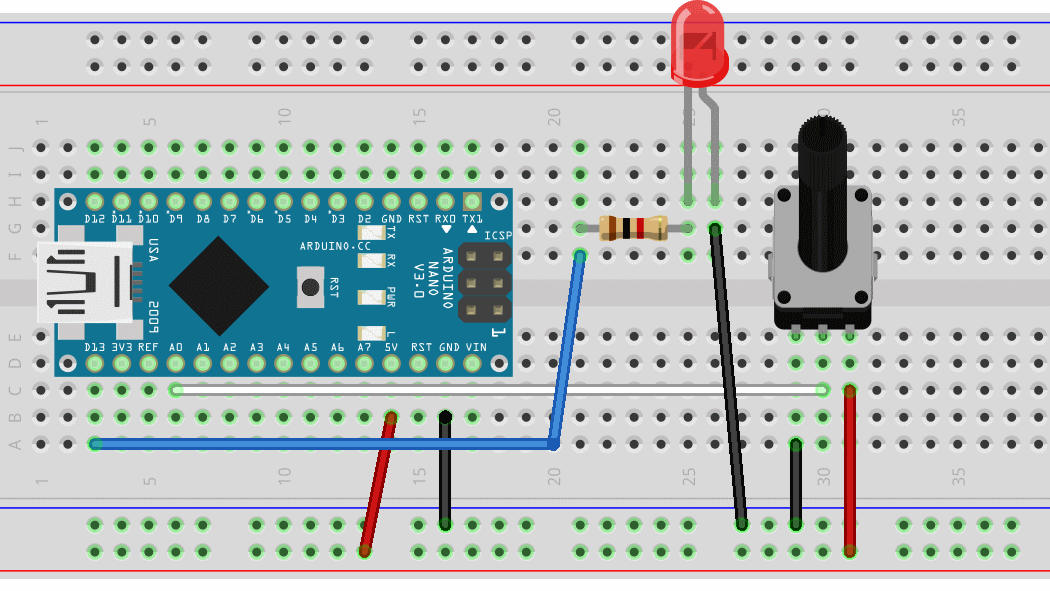
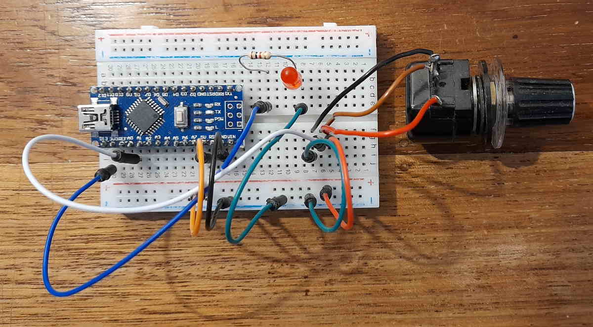
Fritzing (see below) or a photo of your layout aren’t really satisfactory, especially if it has more than a few components.

Many advocate starting by drawing on paper and submitting an image. Here is a typical example. Its readable.

cctdraw

However there are disadvantages to this approach; if you don’t KNOW the right symbol you have no clue what to use to represent the component.

IMPORTANT
The "schematic" above lacks some important information. We have no way of knowing exactly what the "funny diode" is supposed to be.

In addition to the drawing, the schematic should also have

  1. A TITLE - so we know what its supposed to do; and

  2. Details of any "unusual" components like the "funny diode"

Its best if you can provide LINKS to the data sheet or supplier in your post.

Schematic drawing applications
There are many apps that are very easy to use for beginners and can make nice clear *standards-compliant schematics. The main purpose of this tutorial is to introduce you to some that are particularly easy to use.

Both of these will give a useful introduction to more capable (and complicated) apps such as Autodesk Eagle.

* Standards compliant? There are currently TWO important (and different) standards - the ANSI/IEEE ( Y32.2 1975 )symbols used in America and Canada, and IEC60617 used in many other countries (eg UK & Europe)
Of course they are different. It doesnt help that the standards bodies dont make them freely available.
symbols

Diagram Designer
The first schematic app I have used for many years is Diagram Designer - get it here. You will also need the "Electronic Symbols" libraries Here is an example of me using it to make a diagram.

I start by placing my main component - such as the arduino. The standard symbol for complex circuits is a simple box. Then I add more components, the wires to connect them, and finally the labels.

Remember, where you can, INPUTS go to the left, OUTPUTS to the right, positive voltages to top and negative to bottom.

DDnano

Its an old package and the libraries are very limited but does produce good clear diagrams.

TinyCAD (see reply #10) is ALMOST as easy to use, and has a lot more symbols; and lots of instruction files and videos, so you may wish to skip Diagram Designer and move straight to that.

Circuit Diagram (online app)
For more complex circuits a web-based package "circuit-diagram" has a big library of components - including the arduino and rasperry pi modules, and produces nice diagrams.

Components show values and optionally designators – eg VR1. To add random text you need to search for the “label” component.

The component shows pin numbers in their physical place on the module. This is NOT standards compliant for your diagram, (as in not always flowing left to right input -> output) but can be helpful when assembling the final circuit. Compare this diagram with the diagram (Fig4) above to see the difference. Its the SAME circuit.

To place the input (potentiometer VR1) at the left I've needed to run a wire across others. Notice that wires CROSSING dont have a dot, wires JOINING do.

More good resources:

Circuit symbols

Units & Symbols for Electrical & Electronic Engineers - Ebook covering all important standards

and of course wikipedia

7 Likes

From another thread I've seen recommendations for KiCADand EasyEDA. I'll try them out and post updates to this tutorial.

I'm still trying some other CAD/schematic apps I've seen recommended.

TinyCAD

This is an old package, and has a lot of old parts libraries (that you can delete if you wont use them) - eg VALVES. All the libraries that start sm are for surface mount components.

It is very simple to use and behaves consistently with other apps - eg the select, Ctrl-z undo , delete, Ctrl-C Ctrl-V all behave as expected. The diagrams it produces are clear and readable.

The libraries have a search function so adding general components is very easy, and component identifiers and values are easily changed and positioned. Its also easy to make new parts if you cant find a ready-made one.

A point to note is that if the component sidebar is not visible you need to turn on
Options- toolbars - Symbol

I like this, I'd recommend it for beginners as a good way to progress to a more modern and sophisticated app such as Eagle.

There is a very good (albeit dated) guide to using TinyCAD here - But DONT delete the default libraries and install the "Alt" ones.

If you need more symbols you can easily make your own, but there is also an extensive symbol repository where you can search and add symbols to your own "personal" libary and download it.

TCadSolarLogger

And finally - for TinyCAD - my own library of parts for the Arduino; some collected from other sources, some - the Micro Pro, ESP32 and NodeMCU 8266 - I made myself; attached to this reply. Enjoy.
arduino.zip (17.5 KB)

1 Like

This topic was automatically closed 120 days after the last reply. New replies are no longer allowed.

EasyEDA
I tried this package using the online version. https://easyeda.com/
There is a free version you can download and install, but it still requires online access.
Actually the online version has features the downloaded one lacks - particularly the ability to search for user contributed parts - the Nano is the anly arduino in the main library.

As with all the schematic capture packages I've tried it has its own "quirks". If you havent used a schematic capture or cad application previously you can go through the tutorials; otherwise you will soon pick up the "tricks" - such as using the space bar to rotate an object, and right click- move to pan the canvas.

Here is the same circuit again, in EasyEDA

EasyEDA has a good - very extensive - help section here
https://docs.easyeda.com/en/FAQ/Editor/index.html

There is also a good "crib sheet" here

1 Like

Why not just use Fritzing?

Well - its horrible. Although I'm pretty familiar with a few CAD and Schematic capture programs I struggled with Fritzing. However, here are my efforts.

Maybe - for beginners - its a good way to design a simple layout. I couldnt find a symbol for a panel mounted pot.

And you CAN get a "schematic"

I had to manually correct all the wiring, and still notice:
1: Ground at top and 5V at bottom
2: LED label upside down

While I was trying to correct these it crashed my PC.

Eventually - I was able rearrange the schematic
+Vcc at top, GND at bottom, inputs left and outputs right.

This is what it did to the breadboard

I'm NOT a fan. While - perhaps - you can create a decent schematic - after a lot of practice with the app - its easy to do a sloppy job and give up. For anything more complicated than this simple circuit - only 4 components - I'd not use it.

2 Likes

KiCAD (Review contributed by @outbackhut)

This software is only available for download. It is a completely free software, and no where near as limited as many of the other schematic editors. Users can download any package/footprint they like and import it into the software, or they can create their own using the inbuilt symbol editor. This software does not require an internet connection.

If you haven't used a CAD application before, there are a plethora of online tutorials, and a very large KiCAD community and forum. There are relatively few "tricks" - mostly things like a lack of keyboard commands for rotating symbols (a lot of commands are available in the menu that shows up when you right click your mouse), and the need for a proper mouse.

Here is the same circuit again, in KiCAD:

KiCAD has a good and very extensive help section here, which is also available by clicking "help" in the software:

I'm trying it now so I'll add comments as I go.

This tutorial may be useful

3 Likes