Hi, I have a circuit that I want to close or open using input from the serial monitor? I was wondering how you can get values from the serial monitor and how to open and close a circuit using the Arduino. Thanks,
There are examples that come with the IDE.
If you go through them, you will easily be able to do what you need.
Basic reference in general. The software is trivial.
To actually switch the load, assuming it's too large for an arduino pin to drive directly (it probably is):
DC circuits with common ground: Use a MOSFET, preferably an N-channel one switching the low side of the load (p-channel ones to switch high side are more expensive for the same performance, and if the voltage is above 5v, you need another transistor or fet to control it - so only switch high side if you have to).
AC circuits, or where galvanic isolation is necessary, and you don't need to use PWM/dimming: Use a relay.
AC circuits, where you need dimming: Triac+optoisolator.
The examples in serial input basics should be useful.
...R
Will this code work?
sketch_jun04a.ino (417 Bytes)
Use T to format your sketches.
You can attach your sketch using the </> icon in the posting menu.
What happened when your tried the sketch?
.
When I tried it, the relay stayed in the open state, not moving to the closed for some reason. I don't think it is a mechanical issue so I was wondering if I forgot to write anything in the code. Any suggestions?
char serialIn;
#define relay 2
void setup() {
Serial.begin(9600);
pinMode(relay, OUTPUT);
digitalWrite(relay, LOW);
}
void loop() {
if ( Serial.available() )
{
serialIn = Serial.read();
if (serialIn == 'N') {
digitalWrite(relay, LOW);
}
else if (serialIn == 'Y') {
digitalWrite(relay, HIGH);
}
Serial.println(serialIn);
}
}
Your code in reply #4 works.
I would suggest you are not using a driver with the the relay.
Try replacing the relay with a LED and series resistor.
.
Would you show us a photo of your wiring.
Sure,
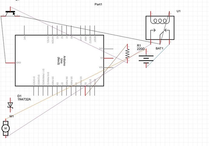
Here is a quick drawing, and a schematic I made using Fritizing.
Note:
- I am using a 5VDC Relay, not a 12 like in the diagram
- I only used a 330 ohm resistor, not a 220 like in the diagram
- I am not actually powering a motor. This is to control a circuit I am building
- I am actually using a 14.8V Lipo-battery
I am not sure whether I wired this correctly. Please help. Thanks,
Looks like you have no relay coil connection to +VCC.
What is the part number to your relay.
A photo of your wiring is best.
I am a little confused. A coil? Also, which part did you need the number for?
There sould be a part number written on the relay.
I can look up the specifications to see the coil resistance, hence the current it requires to operate.
Do you have a web page link where you bought the relay from.
A relay has two coil pins/terminals and three or more contact pins/terminals.
I actually got this relay when I bought my Arduino.
Relay - JZC-11F
5VDC
I think this is it :
12volt coil, it says the pickup voltage is 9 volts not 5 volts.
So is the 12V coil for a 5v relay, or 9v relay?
Looks like you have a 12v relay coil, it will pick at 9v.
This will not work at 5 volts.
Back to your diagram, even if this was a 5 volt relay, your drawing shows no connection to + 5volts.
Also what is the number on your transistor?
.

