I have a TENS muscle stimulation device (Promed TENS 1000S) which I want to control digitally. Right now I'm in the process of wanting to control its output power. On the device it's done with a knob, which is in essence an in-line voltage divider. The issue I'm encountering appears to be yet another example of how I don't understand transistors. I explain this at the end of this post.
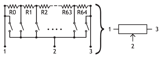
I haven't seen digital potentiometers that could handle 75V (@~80mA). The schematic of a digital potentiometer resistor network is quite easy to understand (see image below)
I've been able to build a crude one with 9 steps and pushbuttons for the latches. Then I replaced the pushbuttons with an NPN transistor (S8050) as seen below but that didn't give me the desired result at all. I can't describe what the output is like, it just seems to be complete jumbled crap readings.
Can I not use a transistor as a switch in this particular case? This is yet again another proof that despite my best efforts, I don't seem to understand when a transistor can or cannot be used as a switch. The transistor blocks current but passes through the resistance regardless? I would very much like to prevent having to use big, heavy, clunky relays. Please advise!
Q1 to Q3 are N-CH Logic Level MOSFETs, these will ensure low resistance switching.
R1 along with R2 and OR R3 and OR R4 will provide your potential divider.
With 3 switches you have 8 levels.
The MOSFETs must have a Vds voltage greater that the peak output of the Tens machine.
The gnd connections need to be there so the MOSFETs have the Arduino control signal and the Tens current as references.
I hope this helps, anyone feel free to suggest modifications, its off the top of my head at 11:00pm.
My last coffee was 6 hours ago.
You would possibly be better off if you simply plugged this circuit into the Tens machine and set its control to whatever maximum level you needed.
@LarryD I get you. Something-something electric currents I'm planning on having one mechanical relay to latch the signal on and automatically disconnect should the microcontroller cease working. Would that achieve the same result (regarding safety), in your opinion?
@LarryD I don't think that's necessary. As-is, without any resistors, the TENS signal is already current-limited coming out of the TENS device, or maybe I'm misunderstanding your intent.
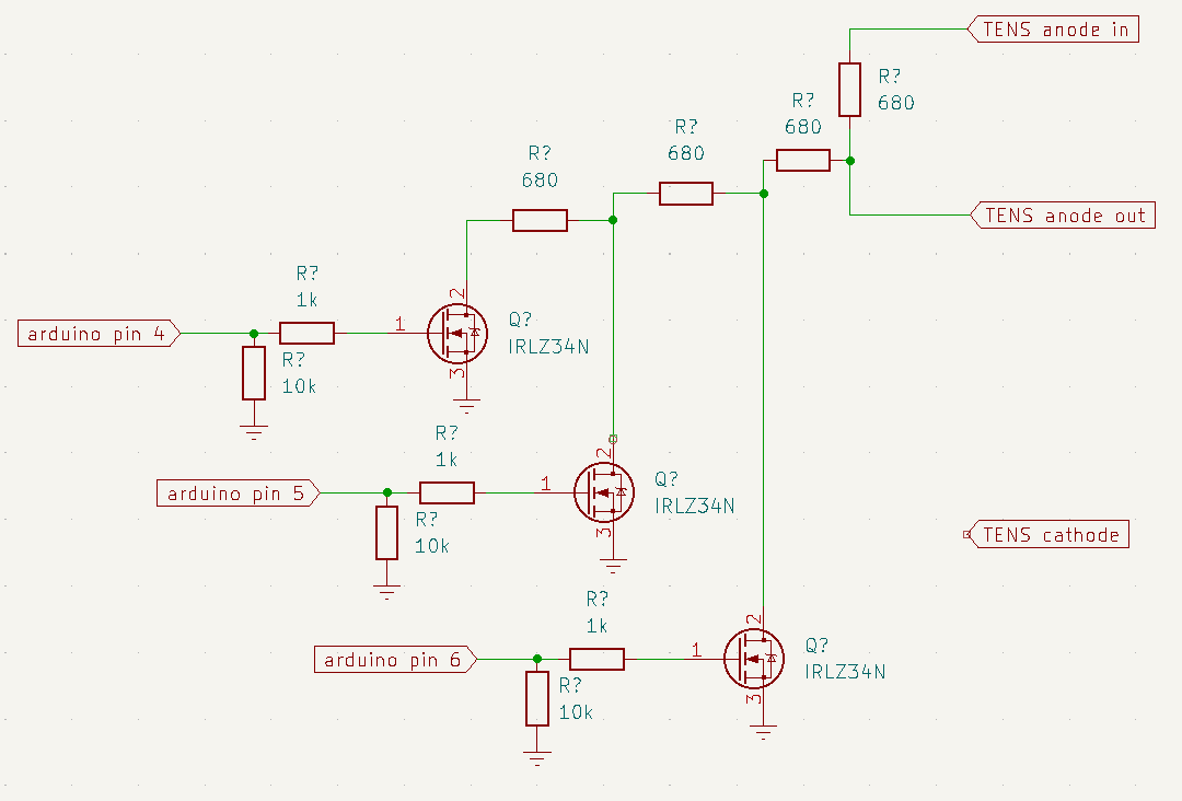
@TomGeorge: I tried your solution and no dice. The TENS signal appear to just bleed through the mosfets if they're open or not. I used three ILZ45N logic-level mosfets rated at 55V and 30A, and didn't crank the TENS device up high enough to exceed that voltage rating. See below my interpretation of your circuit (it helps me practise in KiCad too). I didn't have 470Ω resistors, used 1kΩ instead.
If the output control is left in tact in the Tens machine, then that will be limiting your max output.
What is the value of the pot in the Tens machine?
Probably 50K or so, your 680R will be too small, the Tens output circuit will possibly be a relatively high impedance.
Can you please post a scope image of the signal from the Arduino at the gate of one of the MOSFETs?
@TomGeorge the circuit below works just fine with a regular dc voltage source though! I don't think transistors are meant to deal with AC signals (as the TENS signal does have an AC component to it. Plus the current leakage of mosfets is apparently "a thing"? Take this a grain of salt. At this point my mind had been filled with a ton of information and I can only extract partial wisdoms out of it :-/
Tonight I came across reed relays and those seem super promising regarding ease of use and small footprint. They can be directly driven by Arduino's 5V outputs, require 10ma to turn on, have an internal flyback diode, and the real kicker is they're rated at 200V at 500mA, fits so nicely into my 100V 80mA requirement. Mind you, I haven't received them yet but I'm hopeful at this point.
What do you mean with value from the TENS control? The value of the pot? I don't know, I can't read it faithfully while it's still in the PCB and there's no lables on it. My guess is quite high, maybe 100k?
Yes the 680 is quite low. I got these based on the expectation that I would make a 16-step resistor network, making it roughly 10kΩ. With just 3 steps now I should have used other values.
My Arduino is a Nano. Eventually I'll be switching to an ESP8266. I know things may be different then. For one I have to be efficient with how many pins I use, or I fix that some other way. For my current steps I love the fast turnaround speed of the Nano.
Hi,
Yes 100K or 50K sounds about right, I used to repair some "Beauty Salon" Tens type machines, 8 channel to get rid of cellulite.
They had 47K pots with 75V Zeners across the outputs to limit the pulse height.
If you go to ESP8266 or the even better ESP32, you will be going from 5V logic to 3V3 logic so you will need a small logic level MOSFET or BJT to dive the relays.
But get the basics, proof of concept, up and running with UNO/Nano.
That's cool to know. Did you have nice conversations in the salon while repairing? The zener diode makes sense. I don't see it on this device...
Although you may be right that 680Ω is too little per resistor for a high impedance source, this turned out not to be the reason for not getting the signal through as desired.
I have since received a few mosfet relays (this one), which as I see it are internally like an optocoupler but with an n-channel and p-channel mosfet istead of an NPN transistor. Effectively it enables switching AC and DC sources, and this appears to have made the magic difference for me! The rating of 400V AC/DC at 140mA is also perfect for me. Lovely to have a small package which can handle higher voltages. With these mosfet relays I was finally able to 'dim' the signal of the TENS device.