Hi everyone,
I noticed that when looking at a couple Arduino Nano schematics there seems to be a discrepancy in the RP2 resistor array value!
Take for example this schematic and this schematic.
In the former RP2A/B/C/D has a value of 330 ohm and the former 1K ohm.
I stumbled across this difference as I was trying to explain for myself why a 330 or 1K ohm resistor was used here.
The resistance value difference seems quite big!
I am guessing this difference has to do with the LEDs used which are unfortunately not specified in both schematics and are probably different.
But lets imagine they used these 0805 SMD LEDs. From the data sheet. My attention was drawn to the following table:
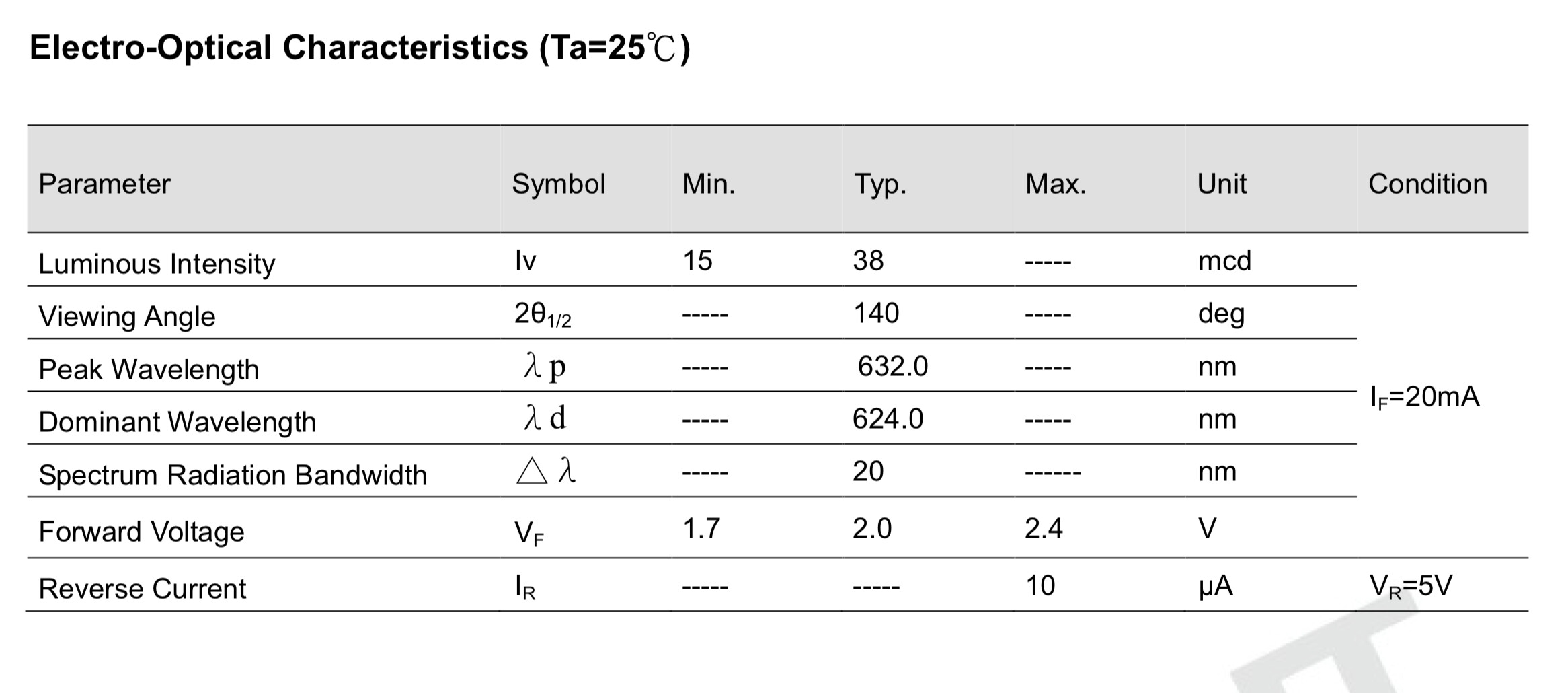
In which some values are nicely provided for operation under 20mA at 25 degrees C.
Typical forward voltage of the LED = 2.0V
R=U/I
the Arduino runs on 5V
the Arduino digital pin has a maximal output of 40mA
5V - 2V = 3V
3V/0.02 = 150 ohm
So resistor with a minimal resistance of 150 ohm should be used to achieve this.
Now let's look at the power rating this resistor should meet.
P = U x I
3V x 0.02A = 0.06W = 1/16,666W
So choosing a 200 ohm resistor with a power rating of 1/10W to be on the save side would be good in this setting?
PS I have no idea if the typical luminous intensity of 38mcd of the led is too bright or dim as an indication LED. Any ideas?