Display ESP32 data on Android phone with BLE

I put here at the beginning the zipped file containing the sketh for ESP32, the .aia file for Mit inventor the LTSpice files (if you want to make the LC circuit) and the compiled .apk app

ZipFiles.zip (5.5 MB)

Hello everyone
I decided to develop this software to avoid using a dedicated touch screen for each project used on ESP32 or Arduino
Especially on Arduino the use of a touch screen takes up a considerable number of pins which are already less than on an ESP32 and very few remain free.
I tested the program both with ESP32 Wroom and with ESP32-D Wroom, the differences I found between the two are that ESP32 must be bound to the phone, while on ESP32-D binding is not necessary, furthermore, when you upload a new sketch on ESP32-D, you do not need to press the reset button every time (really boring), and the serial monitor starts directly.

What you need:

ESP32 or Arduino with BLE
Phone with BLE
Arduino Ide + MIT App Inventor 2 for Android (https://code.appinventor.mit.edu/login/?locale=en) as a browser they recommend using Chrome or Firefox, I, who used the USB connection, found Chrome better, even if every now and then they lose the connection and you have to re-establish it (I recommend closing the app on the phone, then give the reset connection command in the MIT menu and then re-establish a new connection).
If you want to use the project as is, you will need a CL tank circuit connected to ESP32 (pins 16 and 17) and the AD9833 waveform generator that uses the pins SCLK = 18, MISO = 19, MOSI = 23, SELECT = 5 and a pin of your choice (I used pin 4) for the LedC output that can vary the Duty cycle and therefore change the lighting of a LED or the speed of a motor.
The CL circuit allows you to measure the inductance of a connected inductor, in addition to the resonance frequency (useful for example for a metal detector to get the most out of the generated magnetic field) and the cycle length (useful to determine the minimum space between an ON signal and the next).
Unfortunately AD9833, which is great for generating a clean sine wave up to 12500 Hz, does not have commands available to vary the Duty cycle, so for the type of square wave with variable Duty I used the LedC function of ESP32 high speed (up to 19000 Hz with 12 bit resolution) which is used in my sketch if you select 3 as the wave type.
Why Mit inventor and not Android studio or something else?
Because everything runs better and faster and is more accessible to everyone..the only thing I criticize is the automatic saving that cannot be disabled, and this forces you to save your work often, so if you make a mistake it loads the previous version.
Android Studio is always evolving and when you load a program made a year before (always with Android Studio) it generates a ton of errors and you have to waste hours to solve them, if then you try to import pieces of code found online the thing becomes even more complicated also because maybe that instruction is no longer supported by the new Android versions, or because those privacy settings (ridiculous) continue to change.... making programming on that tool truly a stress and a huge waste of time.

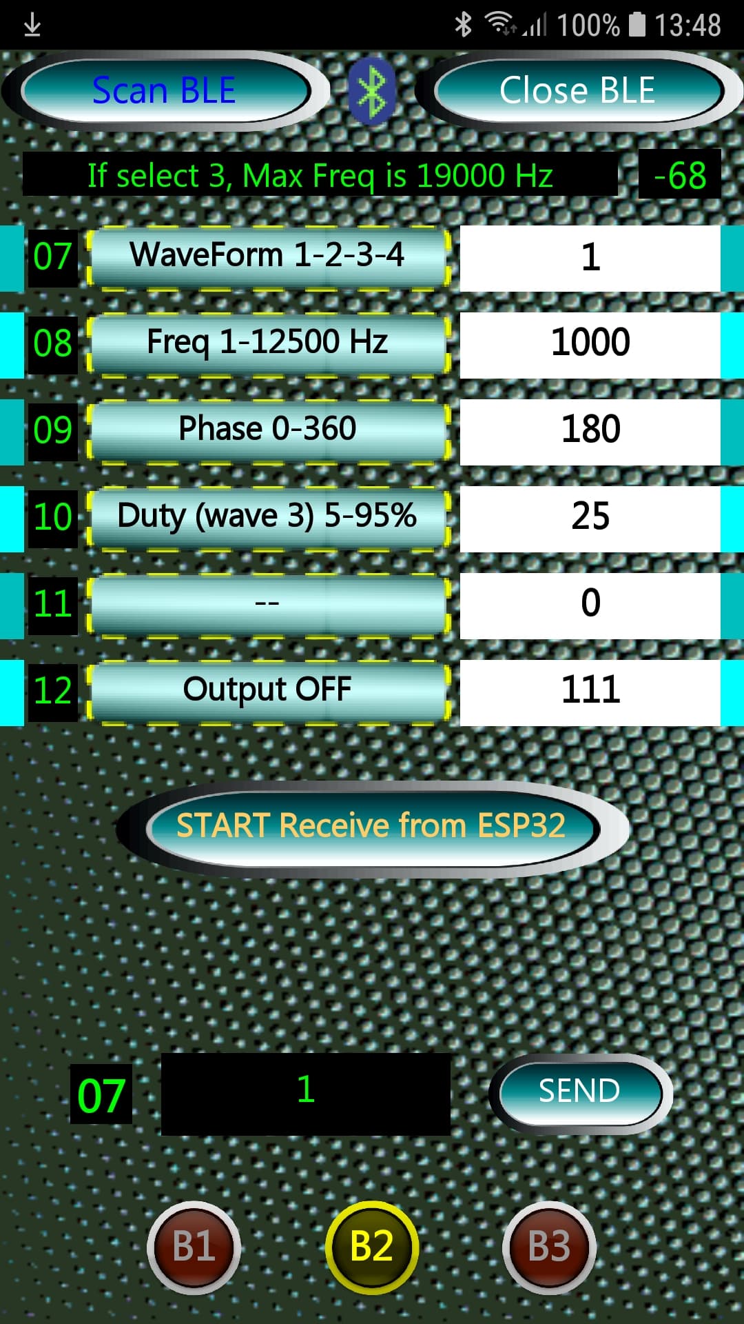
Closing this parenthesis, let's first examine the Android side with this image that displays the first page of the 3 that I have set in the program (selectable with the B1-B2-B3 button on the phone), each page has 6 slots available (you can increase both the buttons and the slots and then review all the code on both the Android and ESP32 sides to adapt it to your needs) and below I include a screenshot of the first page

You can use these pages both to receive data from Arduino (for example, page B1 in my example receives data from the CL circuit connected to ESP32, while page B2 I used to send data to ESP32, so I can select the type of wave of AD9833, frequency etc. (or if I select wave type 3 ESP32 will execute the high speed software routine that is based on the ledc instruction of Espressif, which generates a square wave with duty cycle modifiable), and the Duty selectable in index 10 will only work on wave type 3 because AD9833 does not allow you to set this field.
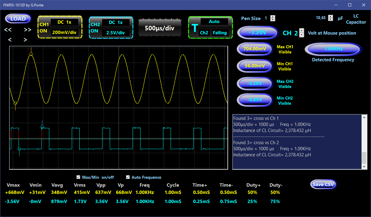
Below I put two images, the first displays page 2 (B2) and the second is taken from the oscilloscope (and then displayed in my program developed in .net) that shows the 2 waveforms activated by the program, in channel 1 a sinusoidal generated by AD9833 and in channel 2 the square wave generated by ESP32 with duty cycle 25%


The files that set the 3 fields of each line are read when the app starts (loaded by the MEDIA section of MIT) and are List1Field.csv List2Field.csv and List3Field.csv.
In MIT, if you click with the mouse on for example in MEDIA List1Field.csv you can download this file to your PC and modify it with a text editor and then reload it after the modifications in MIT with the same name and it will replace the previous one.
The first file (List1Field.csv) is an index list (first column), the second file is the name that will appear on the button (second column) and the third field is the editable data for sending to ESP32 (third column with white background) or to display the data arriving from ESP32.
The third field can be useful to set a starting variable for that given field (if it is a data sending field and not a receiving field), but let's take an example: if for example, on page 2 (B2) in the first line (choice of waveform) 1 is set, by clicking on the WaveForm 1-2-3-4 button, 1 will automatically appear in the text field to be sent, so just press SEND and the waveform change command will send 1 to ESP32, i.e. sine wave selection; if instead you enter 2 in the text field, it will be saved until the app is restarted.
To activate the waveform output you have to press on the waveform selection, otherwise it will remain in OFF mode, and then you can choose the frequency etc..
Unfortunately in the ASSETS we can only read the files and not save them from the program (for example when exiting the app, so we would have found them the same the next time we use the APP) and going to save them in other FileScope (App, Cache, Legacy, Private and Shared) we clash with the various Android versions and with the Privacy settings, so I preferred to use Assets and not other directories scattered on SD, internal memory etc. at least everything remains internal to the app for easier portability on other phones.

Below the 6 lines there is a start/stop button, this is used to tell ESP32 to start sending data through routine1 which is in the main loop, this routine only works if we are viewing page B1 (the page position is controlled by ESP32 which uses routine1 only if page B1 is displayed on the phone), but if you want you can also disable this control, since, through the index of the message sent by ESP32, the data will only arrive at the line of the relative index.

Below this start/stop button there is a label that displays the index to which we will send the data in the text box next to it (clicking on this text box displays a keyboard with only numeric data that we can send to ESP32 by pressing the SEND button).
Also in this case there is a check to see if we are actually on the right page, that is, we can send data to AD9833 only if we are on page 2 (B2).
The text field can send a maximum of 10 digits not exceeding 2147483647.

I have already documented the sketch for ESP32 quite a bit in the rem, let's say that in the initial routines we find the one that interprets the data string arriving from the phone which are practically 2, that is an INDEX (the first 2 characters) and a Value which are the numbers coming from the third column of the phone (text box).
If the second value is null, it is a command string, for example to communicate to ESP32 that I have changed page on the phone (B1-B2-B3).
If instead the second value is present, then it is processed with switch (Identity) {
case...

Other subroutines are for the BLE connection/disconnection and after the SETUP we arrive at the LOOP where the sending of data from the ESP32 to the phone is managed, which in my project only concerns the first page of the program of which I report a screenshot below:

The Loop first checks if we are connected to the BLE and then every second, depending on the ROUTINE variable, jumps to one of the 3 possible routines.
In my example it is only routine 1 that sends data to the first page of the phone and I report the code here:

void routine1() {  // routine 1 that send 3 parameters to phone, so Freq/Period/inductance of CL circuit
  numPulses = 0;
  digitalWrite(16, HIGH);
  Delay(10);  // I charge the capacitor
  digitalWrite(16, LOW);
  delayMicroseconds(30);  // <<<<<<< Time lapse between ESP32 signal end and CL tank circuit oscillation start
  readTime();
  inductance = (float)(pow(1.0 / (6.283185307 * freq), 2)) / capacitance;
  inductance *= 100000L;  // uF
  if (numPulses > 0) {
    stringVal = String(freq);
    T_buff[(stringVal.length() + 1)];  // string + null terminated char
    dtostrf(freq, 1, 2, T_buff);       // 1 is mininum width, 2 is number ofdecimals
    stringVal = String(T_buff);
    stringSend = "01" + stringVal;
    pCharacteristic->setValue(stringSend);
    pCharacteristic->notify();
    Delay(10);
    stringVal = String(Periodo);
    T_buff[(stringVal.length() + 1)];
    dtostrf(Periodo, 1, 0, T_buff);  //1 is mininum width, 2 is precision
    stringVal = String(T_buff);
    stringSend = "02" + stringVal;
    pCharacteristic->setValue(stringSend);
    pCharacteristic->notify();
    Delay(10);

The first part sends a start signal to the CL circuit ( digitalWrite (16, HIGH) ) and then queries the readTime() routine

void IRAM_ATTR isr() {
  unsigned long now = micros();
  if (numPulses == 0) {
    Time1 = now;
  } else {
    Time2 = now;
    detachInterrupt(17);  // disable interrupt after second signal from CL wave
  }
  ++numPulses;
}
void readTime() {
  // Opzioni: DISABLED RISING FALLING CHANGE ONLOW ONHIGH ONLOW_WE ONHIGH_WE (wake up the ESP32 from light sleep)
  attachInterrupt(17, isr, CHANGE);
  Delay(5);
  //formula frequenza = 1 / Periodo
  Periodo = (float)(Time2 - Time1) * 2.0;
  freq = 1.0 / Periodo;
  freq *= 1000000.0;  // Hz
}

which activates an interrupt and examines the changes (CHANGE) on pin 17, and at the second signal the interrupt is interrupted and the length is evaluated and therefore the frequency and induction.
And then this data is sent, one string at a time because the default BLE (but they can be increased) has a maximum of 20 bytes of sending (3bytes of header and 20 of data) and, importantly, a delay is needed (20 milliseconds) between one sending and the next so as not to overload the BLE which is not very fast in sending.
In my example, every 10 readings, I also calculate the average duration of the Period that I need to determine the Calibration, because the circuit also works as a metal detector (5-6 cm away since the start signal coming from ESP32 is only 3.3 Volts and therefore the magnetic field generated by the inductor is really low) and in the Metal Detection field on the phone I will see negative numbers if I bring non-ferrous metals close to the inductor and positive numbers if I bring ferrous metals close.

I think I have listed the essential things of this project, then it is up to you to adapt the MIT part and the ESP32 part to your project, but basically you will have a working BLE connection using only 2 UUIDs, and a very respectable touch display even using an old phone and a considerable energy saving on ESP32 without a display, and many free GPIOs.
I am calmly making a video and will soon put the link below.
Hello everyone and have fun

1 Like

I added the DS18B20 temperature sensor and used the first page where there was the free slot 05 to display it.
I also put the new files here:

ZipFiles2_temperature.zip (6.9 MB)

I'm working on a more complex board and I don't want the post to be closed.
I had serious problems measuring capacitors with ESP32.
Now I'm trying using a 555 and I'm starting to see decent results in detecting the capacitor capacity compared to the frequency emitted by the 555.
Once this is finished I will also publish the PCB and the whole project.
Bye

> Blockquote
this is circuit with ICM7555 for calculate the capacitor, based on this article:
[https://schematicsforfree.com/files/Oscillators%20and%20Generators/Astables/555%20Duty%20Cycle%20Adjustment%20with%20Fixed%20Frequency.pdf
]

I'd like to add a note to this post regarding the resistor values used in relation to ambient temperature, which can affect the results of the measurements.

I used three resistors with a base value of around 5.6K as examples, and here I report the measurements at 28.8 degrees Celsius and 8.8 degrees Celsius, a difference of 20 degrees.

1/4W Metal Film Resistor, 1% Precision

5.636K at 8.8C 5.590K at 28.8C = 0.046/20 = 2.3 Ohm per degree

1/2W Metal Film Resistor, 1% Precision

5.666K at 8.8C 5.636K at 28.8C = 0.03/20 = 1.5 Ohm per degree

3W Cermet Multi-Turn Trimmer Resistor

5.2725K at 8.8C 5.2741K at 28.8C = 0.0016/20 = 0.00008 Ohm per degree

We immediately note that 1/4W resistors are more sensitive to ambient temperature variations (having a smaller layer), while multi-turn resistors are less sensitive to temperature differences.

If our project also includes a room temperature meter and is dedicated to measuring resistors/capacitors/inductors, we can't help but apply these differences to our calculations if we use fixed-value resistors of 1/4 Watt or 1/2 Watt.

If, however, we use multi-turn trimmer resistors made of Cermet material, we can also ignore these temperature differences.

I did this study because I noticed differences in the measurements due to both ambient temperature and the voltage passing through the electrical components (contact and supply resistances) (Joule and Volta effect).

These measurements were performed on a single resistor not connected to the final circuit, because performing them while the circuit is in operation is not easy, and they also vary depending on the quality of the soldering and, above all, the operating current... let's be satisfied with the variation in ambient temperature.

I didn't consider surface-mounted resistors, also because soldering becomes a problem for amateurs. If you don't have space constraints, I'd say the best choice is multi-turn trimmer resistors (unless you want to spend a fortune on thick-film resistors, which have a smaller change in response to ambient temperature variations).

These resistors are also very convenient for calibrating, for example, an oscillator circuit in capacitor measurement (which I'm working on for this project).

And here we are again for a new episode with various improvements, even in the sketch.

So... a stable power supply is ESSENTIAL... and simply connecting a Lipo isn't enough, but after testing various bucks, finally with a very low-noise LT3045 at 500mA, I got stable results in capacitor measurements, in the configuration with 555s in astable mode to generate a square waveform that varies in amplitude depending on the capacitor tested.

And among the various 555s tested (NA555, ICM7555, TS555), I obtained the best results with the Texas TS555, both in the classic configuration with two resistors and with a single resistor, which is also simpler to make, both in terms of components and the formula used in the sketch.

In this link you can find a comparison between these three types of 555s:

And here you can find the link to the circuit in test:

https://www.falstad.com/circuit/circuitjs.html?ctz=CQAg7AnCCsCmC0BGRIDMAOATAOjANk2i0QBZUIIAGPEkPdEKCkS7S99xAKET2hEwlKIXsMJ4ReYaRAlsFdBVR5UYdIvSUSXAO4ChA9YwmYjlLgHlZEEyQbR8+hsPMA3EPDshNk7y5aywvz+rNC6Hl4YtDZo6LTmeqjKsbRJEqiYLuGoWiKmaLk+5gAeHohEZQakwkiqsvogACoAytBtAMIAcgA6AM4Agr0ALgCGAEYANrB90JQApH0AJgCuQwCeXKXw+dASKNBQtIIwAGpcQqgwEJgijjbCQv6YAPqIlILPlM-Fb2O-z6hsIJEHF0MgSGQKLNoJ82JxnkhXlwAMbGQwMGJReqIBDIATyLAHRCYHLvdD4ZxwlAJNHiWlmcKCMS7ERxAQsmmIa7siQxOklMooVAkCRgVIkQ4NRoAUWajT67U2IhINxJN14-BJ-FoIJAACVuFtygx4BBLqhEJdTQ8GsiRgAHEbIgCWowAdsjpr1ugBHPqsPBm0hgPoAKj6BrDfQACrAAE7OgD2iwAFMi1sipgBKcK8PwFWg+VBcOOso4skE67nCHJgTCZXNsrnqpvEkSNnVtrHIG407tdtn1nW57l0ys8lhK1RiCWBFCEG46xe4dBnRLJLGqdJsvv0PIMHJL5znSiXLyWvZ7zB56QQV7vEifb5vC2URCwjjv1ifhHvl5cgEUQLNBMmArEdQQA9sCSGCYMwMBLSIeIqUnPRMTZQ8UlQsCMI3Hdsj3Zs0EI-I+0ccCMgEOtJ0QMVZEo+DFx8IcYBgDgWGwGh0FmDheM-fVYF6Z1hhGD1YAIhgWKxFi+0HY4yFVY4aQlWwGDsGdj1KWZJMDGByCoxc8jQIFKDOTIoDzYkTXPfJkN4lA5AoJznJsHjqRQ1gUG4PQ8x8SzSPCTwGB8IL92w0KrIiA98KAA

I'll explain Let's take a moment to consider the choices made in this circuit:

Power supply for the TS555 chip is 5 volts from an LT3045, because the ESP32's 3.3 volts weren't as precise.

A multi-turn variable resistor (which, as I explained in the previous post, is more stable as the ambient temperature varies) is set to 300kOhms.

You could even go as low as 1Mohm to reduce battery drain. Measurements would be more accurate with very small capacitors (longer cycle), but it would take too long to measure anything around 10uF or higher.

At the output, you can see a voltage divider to lower it to the maximum 3.3 volts that can be applied to the ESP32's digital inputs.

How to calibrate the circuit:

I would say an oscilloscope or a very fast multimeter is essential (don't connect the output to the ESP32 before testing the divider's output).

The ESP32's digital pins consider the output high when the voltage exceeds 2.5V, so you'll need to adjust the divider so that the voltage peaks are between 2.8V and 3.2V to be safe.

The simulator I linked above is quite accurate, but it's always best to check it before connecting the output to the ESP32.

Below is an image of a 10pF capacitor:

As you can see, the edges of the waveform aren't perfectly square (we're at 95kHz), but from 20-30pF onward, we'll have a perfectly square waveform.

Now let's move on to reading the data on the ESP32.

The basic formula in this type of circuit with 1 resistor is Capacitor = ln(2) * R * cycle

which in my sketch translates to capacitance = 0.693147 * 307.22 * ((float)(Period - 5.0) / 100000.0);

But why that Period - 5.0?

Because if you disconnect the capacitor you're testing, you'll still get a default response of 5 uS from the circuit. And if you're measuring capacitors like the one shown above, which has a cycle of 10.5 uS, if you don't remove this 5 uS, you'll get a completely incorrect reading, while there's no problem with capacitors with a much higher cycle.

And I honestly haven't found this correction in any online example, and if you don't apply it, you'll get incorrect measurements with small capacitors.

We'll call this dead time, and if you change the value of resistor R1, you'll need to factor this time into the formula and measure it without the capacitor.

You can use ESP32 to measure this dead time; for example, just change the line if (Period > 6) { to if (Period > 1) { and remove the capacitor being tested.

Now I'm uploading the sketch to measure only the capacitor. I'm also changing the induction measurement method (using a Colpitt LC oscillator), and I'm thinking of eventually making a PCB that combines the two and sends the data to the phone via BT.

// Connettere l'uscita Pin3 del TS555 al pin 4 di ESP32 con partitore di tensione per avere <3.3V
#include "esp_intr_alloc.h"
#define ESP_INTR_FLAG_LEVEL3 (1 << 3)  ///< Accept a Level 3 interrupt vector
volatile unsigned long Time[3];
unsigned long now;
long Periodo, TotPeri;
int numPulses, Letture, Divisore;
float freq, capacitance, TotCapacitance, MediaCapacitance, FreqMedia, TotFreq, MediaPeriodo;

void setup() {
  Serial.begin(115200);
  Delay(1000);
  pinMode(4, INPUT);
  Serial.println("OK");
  gpio_dump_io_configuration(stdout, SOC_GPIO_VALID_GPIO_MASK);
  Delay(200);
}
void IRAM_ATTR isr() {
  numPulses++;
  now = micros();
  Time[numPulses] = now;
  if (numPulses == 2) {
    detachInterrupt(digitalPinToInterrupt(4));  // disattivo interrupt dopo il secondo segnale
  }
}

void loop() {
  numPulses = 0;
  Time[0] = micros();
  // Opzioni: DISABLED RISING FALLING CHANGE ONLOW ONHIGH ONLOW_WE ONHIGH_WE (wake up the ESP32 from light sleep)
  attachInterrupt(digitalPinToInterrupt(4), isr, RISING);
  while (numPulses < 2) {
    delayMicroseconds(1);
  }
  Periodo = (Time[2] - Time[1]);
  if (Periodo > 6) {
    Letture++;
    freq = 1.00 / Periodo;
    TotPeri += Periodo;
    TotFreq += freq;
    // Logaritmo Naturale di 2 = 0.693147
    // R1=307.22 singola resistenza
    capacitance = 0.693147 * 307.22 * ((float)(Periodo - 5.0) / 100000.0);  // 95.4546KHz Periodo 10.50 Capaci 11.712pF  con codensatore 10pF
    TotCapacitance += capacitance;
    MediaCapacitance = ((float)TotCapacitance / Letture);
    MediaPeriodo = (float)TotPeri / Letture;
    FreqMedia = (float)TotFreq / Letture;

    if (Letture > 5) {
      FreqMedia *= 1000000.0;
      Serial.println("");
      Serial.print("*********  ");
      if (FreqMedia > 1000) {
        Serial.print((FreqMedia /= 1000.0), 4);
        Serial.print("KHz   Periodo ");
      } else {
        Serial.print((FreqMedia), 4);
        Serial.print("Hz   Periodo ");
      }
      Serial.print(MediaPeriodo, 2);
      Serial.print("   Capaci ");
      if (MediaCapacitance > 1000) {
        Serial.print((MediaCapacitance /= 1000.0), 4);
        Serial.print("uF");
      } else {
        if (MediaCapacitance > 1) {
          Serial.print((MediaCapacitance), 4);
          Serial.print("nF");
        } else {
          Serial.print((MediaCapacitance *= 1000.0), 4);
          Serial.print("pF");
        }
      }
      Serial.println("  *********");
      TotPeri = 0;
      Letture = 0;
      MediaPeriodo = 0;
      MediaCapacitance = 0;
      TotCapacitance = 0;
      FreqMedia = 0;
      TotFreq = 0;
      Delay(2000);
    } else {
      freq *= 1000000.0;
      if (freq > 1000) {
        Serial.print((freq /= 1000.0), 4);
        Serial.print(" KHz ");
      } else {
        Serial.print((freq), 4);
        Serial.print(" Hz ");
      }
      Serial.print("  Periodo ");
      Serial.print(Periodo);
      Serial.print("uS");
      Serial.print("  Media ");
      Serial.print(MediaPeriodo, 2);
      Serial.print("  Capaci ");
      if (capacitance > 1000) {
        Serial.print((capacitance /= 1000.0), 4);
        Serial.println("uF");
      } else {
        if (capacitance > 1) {
          Serial.print((capacitance), 4);
          Serial.println("nF");
        } else {
          Serial.print((capacitance *= 1000.0), 4);
          Serial.println("pF");
        }
      }
      Delay(100);
      Periodo = 0;
    }
  } else {
    Serial.print(".");
    Periodo = 0;
    TotPeri = 0;
    Letture = 0;
    MediaPeriodo = 0;
    MediaCapacitance = 0;
    TotCapacitance = 0;
    FreqMedia = 0;
    TotFreq = 0;
  }
  Delay(100);
}
void Delay(unsigned long timeToWait) {
  unsigned long adesso = millis();
  while ((millis() - adesso) < timeToWait)
    ;
}
// void initWiFi() {
//     WiFi.mode(WIFI_MODE_STA);
//     if(!WiFi.config(local_IP, gateway, subnet, primaryDNS, secondaryDNS)) {
//       Serial.println("Non riesco a configurare la modalità station (STA)");
//     }
//     WiFi.begin(WIFI_SSID, WIFI_PASS);
//     Serial.printf("In connessione a %s .", WIFI_SSID);
//     while (WiFi.status() != WL_CONNECTED) { Serial.print("."); delay(200); }
//     Serial.println("connesso!");
//     IPAddress ip = WiFi.localIP();
//     Serial.printf("SSID: %s\n", WIFI_SSID);
//     Serial.printf("Canale: %u\n", WiFi.channel());
//     Serial.printf("IP: %u.%u.%u.%u\n", ip & 0xff,
//     (ip >> 8) & 0xff, (ip >> 16) & 0xff, ip >> 24);
// }

As you can see, I use GPIO D4 as a read input. I noticed that this pin has a more precise response to interrupts, perhaps because it is already set to a higher priority than other pins, as this pin can be used as a touch signal (as well as D2, for example).

The sketch waits for two high signals to arrive and then sets the corresponding period in uS and the resulting frequency.

The individual sampling results are displayed, or the average of the results is displayed every five readings.

As you can see, the data matches the oscilloscope image, namely:

95.4546KHz Period 10.50 uS Capacitance 11.712pF with 10pF ceramic capacitor

If you want to increase the precision for small capacitors, you'll need to increase the resistance.

See you next time...and have fun!

Now let's move on to the inductor reading part because I'll eventually present a PCB that will include both circuits, selectable via a switch: capacitor and inductor reading and displaying results on a phone app via Bluetooth.
Most mid-range and budget testers don't have an inductor reading, and since some don't even have a capacitor reading, I combined both functions.
I tried various examples on the web with disappointing results in terms of accuracy.
I had the opportunity to test both LC and Colpitt circuits and ultimately used the Colpitt to generate a sinusoidal waveform that varies depending on the inductor and capacitors connected in the tank loop.
The result was decent right from the start, but I had to test various configurations with both transistors and ICs to find the one that best suited both small and large inductors.
In the photo below, I've shown the results of testing a 47,000 mF inductor, which I also used as a basis for calibrating the two main resistors in the circuit (R1 and R2).

As you can see, the results on the ESP32 are identical to those displayed on the oscilloscope.
To ensure a long enough duty cycle to reduce reading errors even with relatively small inductors, and to be read more accurately by the ESP32 using interrupts, you need a NON-ELECTROLYTIC capacitor of approximately 32-33 uF or greater (the higher the duty cycle, the lower the chance of error).
Unfortunately, these measurements are not available among metal-layer polyethylene ones, except in rare cases at exorbitant prices. Therefore, I created two banks with four 8 uF capacitors connected in parallel, ensuring that the total measured values ​​are similar.
High-voltage capacitors aren't needed, because the Colpitt circuit, unlike the LC circuit, doesn't generate voltage/current fluctuations from a 5V 0.5A input except at the first input until the circuit stabilizes.

In this photo, you can see three of the inductors I examined. I used the first one (marked 47mH+47mH) to calibrate the circuit with the two resistors R1-R2. Once calibrated, the inductor I made for a metal detector (number 3 in the photo) also matched the values ​​reported by my program, which I used to build it and which is based on mathematical formulas.
Number 2 in the photo is the smallest of the three; it isn't marked with values, and with my circuit, it tells me it's 10.3406 uH.
Below, you can see the 32+32 uF capacitor bank I used in the circuit.
For power, I used a 12V 1A Lipo battery and the LT3045 circuit, the photo of which is below (you can search for photos online and decide where to purchase it).

The power consumption is quite high in this Colpitt mode, and when the battery drops below 11.5V (from 12.6V at full charge), I noticed the readings change slightly. Therefore, this LT3045 circuit doesn't seem to adapt to the voltage changes. However, when the power supply is sufficient, the output is truly noise-free, so much so that you might consider powering it with a 220V>12V power supply if you're using it in a bench test and verifying that the output is equally clean.
Let's now examine the ESP32 sketch, which is derived from the one used for measuring capacitors. The routine that uses interrupts (I always used pin D4, which is more precise than other non-touch-sensitive pins) reads the time in microseconds between the first reading of the rising edge (which, as I recall, is between 2.5V and 3.3V) and the second, and then establishes the duty cycle and the resulting frequency of the input signal with the formula Frequency = 1/Duty Cycle. The inductance is then calculated with the formula:
inductance = ((float)(pow(1.0 / (6.283185307 * freq), 2)) / capacitance) / 1000.0; // in milliHenry
of which 6.283185307 is 2 times pi, freq is the frequency, and capacitance is calculated in the variable declaration at the beginning of the sketch and comes from the calculation >>> (capacitor 1 * capacitor 2) / (capacitor 1 + capacitor 2)
The two capacitor banks must be measured disconnected from the circuit, and it is essential that their capacitance reading in Farads is as accurate as possible.
Since I used capacitors that cost a few euros for 50 pieces, after placing them under load in the circuit, I removed them and measured them a second time. For this reason, it is convenient to have them inserted into an IC base and not soldered to the circuit (as you can see in the previous photo).

Calibration
The values ​​of the two resistors (R1-R2) that I reported in the LTSpice circuit (140 Ohm and 57.24 Ohm) are indicative, because everything depends on the soldering, wiring, and the transistor used. Therefore, you need to use 1K multiturn resistors for the first (R1) and a 100Ohm multiturn resistor for the second (R2). By working with these, our ESP32 should return a duty cycle similar to that resulting from the mathematical operation (6.283185307 * Sqrt(Henry * capacitance)) * 1000000.0
in which 6.283185307 is twice the pi
multiplied by the square root of the Henrys of our inductor multiplied by the capacitance, which was calculated at the beginning of the sketch as I said before on the value of the two capacitor banks.
In the zip file, I've included a small program to automatically calculate the duty cycle. Simply enter your capacitor bank values ​​and your inductor, whose value in microhenries you know, in the yellow (editable) fields. I compiled it in .NET Framework mode, Version = v4.8.1, so it works from Windows Vista onwards.
So, by looking at the value in the ESP32's serial monitor (the cycle duration) or with an oscilloscope, you can adjust R1 and R2 so that they are similar in microseconds to those resulting from the mathematical operation.
Resistor R3 is a 10K multiturn resistor; a value around 2K should be fine, but if you see an incorrect value in the serial monitor's inductance calculation, try increasing or decreasing it. This may be because output 1 of the comparator isn't sufficient to drive the ESP32's input.
To recap: to check the length of the duty cycle, it's best to use an oscilloscope connected to pin 3 of the transistor (don't connect D4 of the ESP32 to this pin because the voltage is much higher than the 3.3V supported by the ESP32). To check the comparator output, you can also check the result with the ESP32, because depending on how you adjust R3, the current will be sufficient to drive the ESP32's input or not.
The sketch performs 5 measurements and then averages the results, and as you can see from the first image, the results are identical out of 5 measurements, so I'd say it's a good result. However, some small variations can be observed when the battery voltage drops below 11.7V.

I'll soon develop the PCB that contains both the capacitor meter and the inductance meter, which can be selected with a selector switch, so that the probes are the same for the two circuits, and the power supply will only feed one of the two circuits to conserve battery power.
In the zip file, you'll find the .ino file for Esp32, the calculation file, the LTSpice file, and the images.

Hi!

Articolo Induttore.zip (802.9 KB)