I did not find anything 100% identical, gere in the forum.
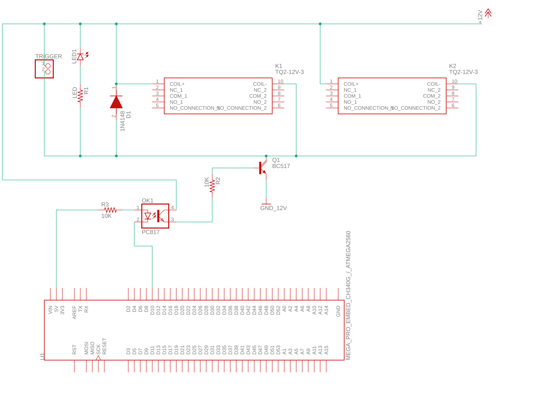
I want to switch 12V Audio Relais on a DIY PCB with a Mega Pro.
Also the LED should light up and the trigger headder shall provide 12V DC up to 150mA.
Would this one work with these commands like the ready to go 12V modules?
int eightChanRelayIN1 = 11;
digitalWrite(eightChanRelayIN1, LOW);
(I know it is not a complete scetch.)
Add an additional diode across the coil of the second relay, just like the first one.
I expect it will work marginally as-is because OK1 requires significantly more drive. I suggest replacing the current resistor with something in the 300-ohm range.
Similarly, replace R2 with a resistor in the 1k range.
The transistor is a darlington, and the two relays are drawing 24mA total.
A 10k base resistor is good enough for that.
Why use a darlington. A BC547 would do.
For a BC547/8 the Ic:Ib ratio should be ~20:1 (10k could still work for 24mA).
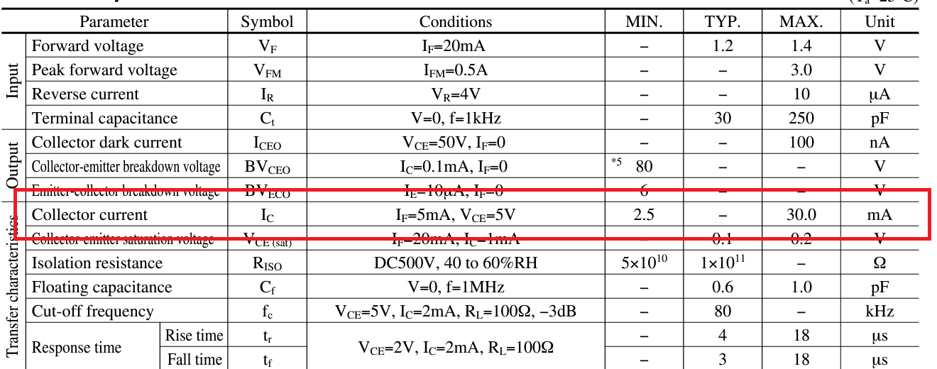
Opto LED current should be twice the opto collector current (Google "opto ctr"), so 10k is too high. Calculate with Vf of the LED@1.2volt. 2k2 seems the right value for the LED.
You could omit the opto coupler if you can share the relay supply with Arduino ground.
Just connect the base resistor directly to the Arduino pin.
Leo..
If the CTR (current transfer ratio) of the opto coupler happens to be bad, then the opto LED could need twice the current of the opto transistor. To switch two relays (24mA), the required LED current could be 48mA. Too much for an Arduino pin.
One relay per opto, and an opto with high CTR would be ok.
Another thing to consider is the combined Arduino pin current for many relays (OP's requirement).
Leo..
If the 12V supply is part of the audio system then using a PC817 is a very good idea because it keeps the two grounds separate.
Ground loops and long ground wires can pick up 50/60 Hz hum and you will here it in your audio system
The opto is redundant. Transistors are generally bad match with Arduino because they are current hog and Arduino's pin current output is small. The best is a TO-92 MOSFET like 2N700 or similar MOSFETs with average size and adequate current handling with . It is also better to power each one of those relays with a separate MOSFET.
So, 12V will not be part of the Audio Path.
The 5V / 12V and Audio circuts with their own GNDs will be completely seperated.
Regarding the consumption, I could also use Relais with less consumption (half), but over all, I have to:
Switch 2 relais for audio (so 4 shifting points since I want to de-connect signal GND completely).
Turn on an LED.
Turn on 12V on a connector.
(Normally these outputs are rated as 150mA max.)
Over all I'll have about 10 of these circuits + several single relais , display, encoder etc.
As I'm not that deep in the topic, is there a smart way to handle it?
I mean I could only drive one 12V relais with the Arduino that shifts then all these stuff with 12V but it feels a little un-sexy😅
Yes, it will be a complete PCB with an Arduino Mega Pro that will have a socket on the PCB.
I started with the normal relay modules that you can buy and had the intention to let them shift the Audio relays.
The code is nearly done for that and I was about to plan the orders.
But I came to the point within the weekend to realize that this would end in a big jumpercable chaos and will cost massive space within any hifi devices I want to install that.
Since I need to do a PCB anyhow for the Muses and the Audio relays, I'll step up now and make it the right way.
About the GNDs:
The Signal GND will just be shifted by the Relais, with no direct contact to the controlling circuits.
There might be a connection between the 5V GND of the Arduino at the Muses volume control, but I'm just starting there.
With an optocoupler 12V would be also isolated from 5V.
I plan to not cascade the PSUs and want to create them seperated with individual windings on the transformator.
Did you consider a Nano and a couple of TPIC6B595 shift registers.
TPIC chips can drive eight 12volt relay pairs directly, no other parts needed.
Leo..
Yes, I considered the Nano, since the Idea with a socket would work much better with it.
But from my previous projects I'm pretty sure it will run out of storage with all the stuff I have in mind.
(I already had another project, where I needed to switch from the Uno to the Mega.)
Also the pin ammount will be an issue.
I have already 10 pins for control elements.
Even if I would go with the TPIC6B595 (might be an interesting idea) I would need at least 2x TPIC6B595 and then I'm already out of pins.
Points like aditional module based relays for 230V switching and the Muses volume control not even counted😅
Oh, and yes, I know that the LED is the wrong way around
Shift registers are cascaded, so many use the same number of Arduino pins as one.
74HC595 or 74HC165 shift registers can also be added to that same chain.
Let's simply agree that it is even then much too less pins. Also a Nano Every costs more than a Mega Pro.
So I will stay with the Mega Pro
To come back to the general questions and I'll try to wrap them up:
Add an additional diode across the coil of the second relay, just like the first one.
I do not see the need, since the two couls are in parallel so the diode is already across both.
Why use a darlington. A BC547 would do.
With the option that the trigger headder might grab up to 150mA (but might also be not even connected), I assume here a max consumption about 200mA.
Since I'm not that deep into the resistor calculation for these transistors, how do I need to size it with such a range of consumption?
Or would be really a MOSFET here the better choice?
Another way would be to not switch the trigger parallel with the relais, but with a 3rd relais.
With this the consumption on the transistor would be less and more constant, since the 3rd relais would switch, regardless if there is something connected to the trigger.
Also with this, the point to drive all through the opto itself is off the table.
At 200mA a 2N2222 (BC337) has a saturation voltage of 0.1volt with a (minimum required) base current of 3mA. A BC517 darlington drops 0.8volt at that current, and dissipates 0.16watt, but only needs 0.2mA base current. A 2N7000 (no drive current) would drop 0.4volt. A BC547 is a poor choice for 200mA. They all will do the job. Your choice.
Leo..
So I tried to digg a little deeper into this.
You are right a BC337-40 should be the better choice (I just wonder why Mouser is so expensive on these, but anyhow, I have a German dealer here that has it for 4 Cents.
Since I want to make it switch about up to 200mA the base resistor should be about 11k, put a little spare and the 10k fits.
My question is, will I have a problem with 10k if the load is just about 45mA (the two relais and the LED)?
Regarding the PC817, I found some comments that it is not a very good one, but I see them often in use with arduinos.
Is there a replacement I should keep in mind?
(I did not found much about that.)
About the resistor for the coupler, I end up with an optimum of about 190R (5V supply 1,2V for the LED with 20mA).
So I assume you ment 220R instead of 2k2?
Not a problem. A base current of 5-10% of max expected collector current is common for switching. 3mA for 200mA is just the absolute minimum to fully saturate. See the saturation graph in the transistor's datasheet.
An opto coupler is a basic part. Don't worry too much about it.
If you do, then get the ones that have been selected for CTR.
The LED can also be in series with the base resistor, which saves parts and current.
I meant 2k2, before I knew you were going to switch 200mA.
220 ohm is 17mA through the opto LED, and good for almost 10mA opto transistor current.
Use 330 ohm, and call it a day.
Leo..
Last question: Are the Coupler and Transistors known to fail or very heat sensitive when it comes to soldering?
(Some audio transistors are very heat sensitive.)
I think if I should go with socket for them.