DIY nano with Serial programmer

Hi All,

I have a Atemga328p working OK on a DIY board, I can program the bootloader onto the MCU using the ISP and I would like to program it using the Arduino IDE via a USB adapter.

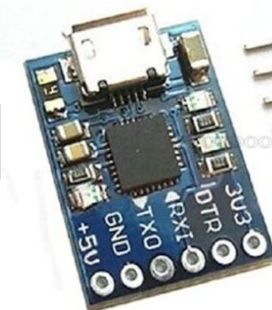
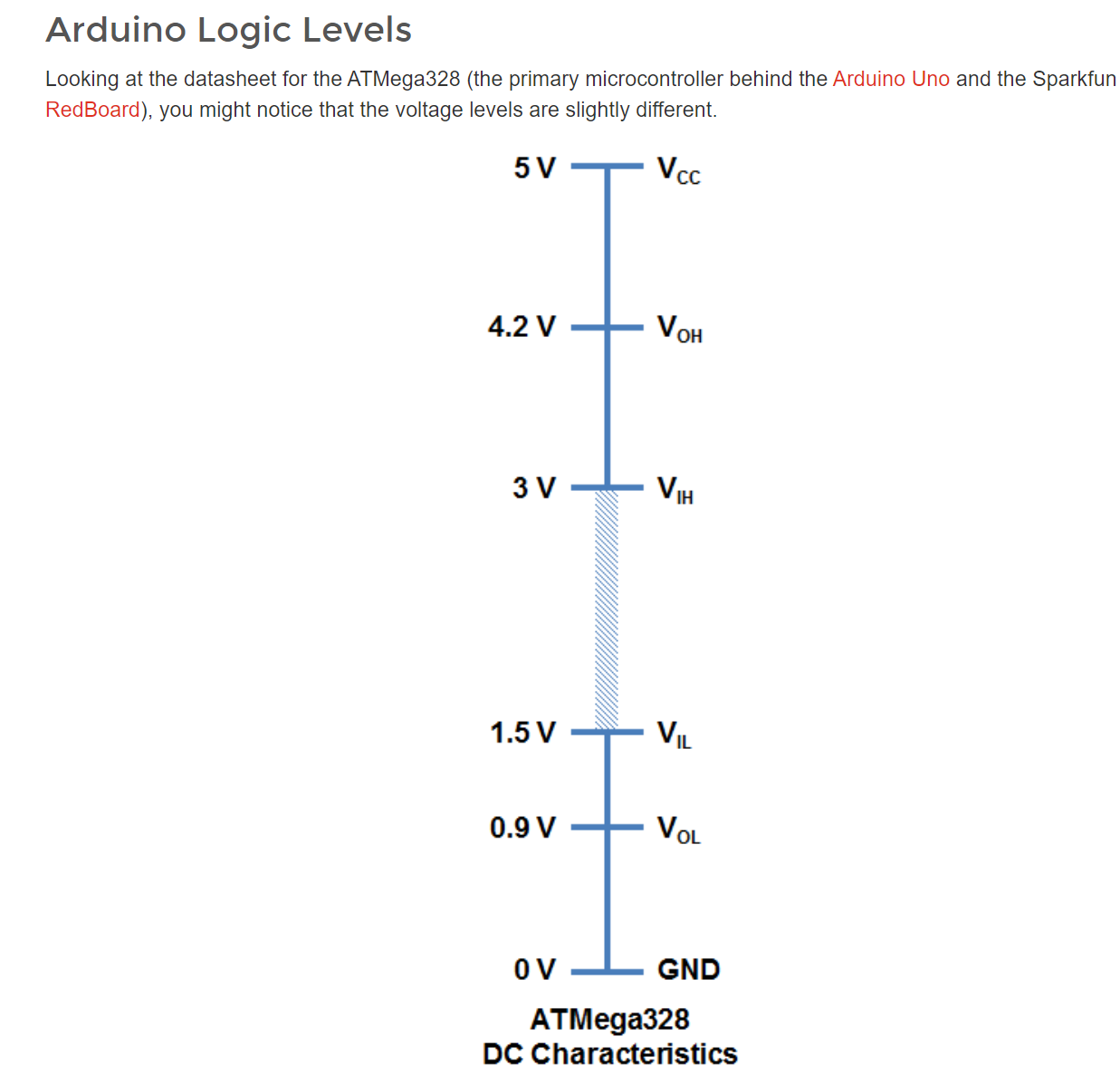
So, I purchased a USB to Serial adapter from ebay but this fails to auto-reset the MCU (using DTR)! after lots of reading I think it is because the USB adapter is a 3.3v device and this has issues when running with my 5v DIY board.

  • Is there an easy way around this?
  • another 5v USB adapter I can purchase?
  • maybe it's possible to use a FTDI TTL-232-5v?

Thanks

Gammon Forum : Electronics : Microprocessors : How to make an Arduino-compatible minimal board

I have seen 5V only serial-USB and 5V/3.3V selectable units. Are you sure you have 3.3V only?

Hi,

Here is the one I purchased, it has 3.3v and 5v supplies but I cant see a selector voltage. unless I'm loosing the plot!

>>USB adapter<<

USB connector is supplied +5 from PC

Bottom solder connector allows you to select +5 OR 3V3 to match your Arduino board

Hi,

When you say botton solder connector you can select 5v or 3.3v do you mean the header "5v, gnd, tx, rx, dtr, 3.3v'

If you do, arn"t these just outputs?

I have connected the RX TX DTR GND AND 5V to my DIY board, my DIY board is also powered by an external 5v supply. When I check the RX, TX and DTR they are 3.3v. I read that having these at 3.3v causes the issue I have. However there was no explanation for a fix in the post.

Steve

Hi,

Do you mean thee is a way of selecting a logic level for the RX,TX,DTR pins? currently they are 3.3v and I cannot see a solder pad/jumper to change this?

I can see 3.3v and 5v but I thought these are simply outputs.

There are a number of configurations on these adapters:

  • USB is 5V and T output is at 5V logic
  • USB is 5V and T output is at 3V3 logic
  • many boards have solder jumpers for logic
  • many boards have pin jumpers for logic

Your board has a 3V3 regulator driven from USB 5V so it can be used to supply low current to a uC or to a logic-level converter such as:
SparkFun Logic Level Converter - Bi-Directional - BOB-12009 - SparkFun Electronics

The Internet has lots of references:
Arduino reset DTR issues at DuckDuckGo

I personally have not experienced the issue, but Sparkfun suggest this witing for their Arduino USB-serial:

You may find this post of interest:

Added: pic of various modules...

The 2-left ones are my goto with the center one an easy jumper.

Although more pricy, you get convenience from switchable voltages:
SparkFun USB to Serial Breakout - FT232RL - BOB-12731 - SparkFun Electronics

And, I strongly recommend using (or similar):
SparkFun Logic Level Converter - Bi-Directional - BOB-12009 - SparkFun Electronics

Read & understand this and be wise:

Logic Levels - SparkFun Learn

For simple interfacing, with added stray capacitance, review:

Voltage Dividers - SparkFun Learn

And while cheap and easy to construct, this is only recommended for quick-and-dirty testing although one can find it in commercial h/w:

Note: not a recommendation for purchasing, just they have nice, easy to understand graphics.

Added:
About DTR reset and home-brew Arduino board:

Arduino from Scratch Part 11 - ATMEGA328P DTR and Reset (rheingoldheavy.com)

OK, I purachsed a sparkfun "SparkFun FTDI Basic Breakout - 5V" but it still does not work!

Here is the schematic

My Board <-------> Spartfun Board
DTR <-------> DTR
Rx <-------> Tx
Tx <-------> Rx
5v <-------> 5v
GND <-------> GND
Not connected <-------> CTS

This is the Arduino IDE output:

avrdude: stk500_recv(): programmer is not responding
avrdude: stk500_getsync() attempt 1 of 10: not in sync: resp=0xb3
avrdude: stk500_recv(): programmer is not responding
avrdude: stk500_getsync() attempt 2 of 10: not in sync: resp=0xb3
avrdude: stk500_recv(): programmer is not responding
avrdude: stk500_getsync() attempt 3 of 10: not in sync: resp=0xb3
avrdude: stk500_recv(): programmer is not responding
avrdude: stk500_getsync() attempt 4 of 10: not in sync: resp=0xb3
avrdude: stk500_recv(): programmer is not responding
avrdude: stk500_getsync() attempt 5 of 10: not in sync: resp=0xb3
avrdude: stk500_recv(): programmer is not responding
avrdude: stk500_getsync() attempt 6 of 10: not in sync: resp=0xb3
avrdude: stk500_recv(): programmer is not responding
avrdude: stk500_getsync() attempt 7 of 10: not in sync: resp=0xb3
avrdude: stk500_recv(): programmer is not responding
avrdude: stk500_getsync() attempt 8 of 10: not in sync: resp=0xb3
avrdude: stk500_recv(): programmer is not responding
avrdude: stk500_getsync() attempt 9 of 10: not in sync: resp=0xb3
avrdude: stk500_recv(): programmer is not responding
avrdude: stk500_getsync() attempt 10 of 10: not in sync: resp=0xb3
Problem uploading to board. See https://support.arduino.cc/hc/en-us/sections/360003198300 for suggestions.

Scope picture of reset line from my board

Scope picture of reset line from a standard Nano board

Also here is the verbose output of the bootloader programming using AVRISP MKII and "Burn Bootloader" option in Arduino IDE

avrdude: Version 6.3-20190619
         Copyright (c) 2000-2005 Brian Dean, http://www.bdmicro.com/
         Copyright (c) 2007-2014 Joerg Wunsch

         System wide configuration file is "C:\Users\user\AppData\Local\Arduino15\packages\arduino\tools\avrdude\6.3.0-arduino17/etc/avrdude.conf"

         Using Port                    : usb
         Using Programmer              : stk500v2
avrdude: usbdev_open(): Found AVRISP mkII, serno: 000200175658
         AVR Part                      : ATmega328P
         Chip Erase delay              : 9000 us
         PAGEL                         : PD7
         BS2                           : PC2
         RESET disposition             : dedicated
         RETRY pulse                   : SCK
         serial program mode           : yes
         parallel program mode         : yes
         Timeout                       : 200
         StabDelay                     : 100
         CmdexeDelay                   : 25
         SyncLoops                     : 32
         ByteDelay                     : 0
         PollIndex                     : 3
         PollValue                     : 0x53
         Memory Detail                 :

                                  Block Poll               Page                       Polled
           Memory Type Mode Delay Size  Indx Paged  Size   Size #Pages MinW  MaxW   ReadBack
           ----------- ---- ----- ----- ---- ------ ------ ---- ------ ----- ----- ---------
           eeprom        65    20     4    0 no       1024    4      0  3600  3600 0xff 0xff
           flash         65     6   128    0 yes     32768  128    256  4500  4500 0xff 0xff
           lfuse          0     0     0    0 no          1    0      0  4500  4500 0x00 0x00
           hfuse          0     0     0    0 no          1    0      0  4500  4500 0x00 0x00
           efuse          0     0     0    0 no          1    0      0  4500  4500 0x00 0x00
           lock           0     0     0    0 no          1    0      0  4500  4500 0x00 0x00
           calibration    0     0     0    0 no          1    0      0     0     0 0x00 0x00
           signature      0     0     0    0 no          3    0      0     0     0 0x00 0x00

         Programmer Type : STK500V2
         Description     : Atmel STK500 Version 2.x firmware
         Programmer Model: AVRISP mkII
         Hardware Version: 1
         Firmware Version Master : 1.24
         Vtarget         : 5.0 V
         SCK period      : 8.00 us

avrdude: AVR device initialized and ready to accept instructions

Reading | ################################################## | 100% 0.00s

avrdude: Device signature = 0x1e950f (probably m328p)
avrdude: erasing chip
avrdude: reading input file "0x3F"
avrdude: writing lock (1 bytes):

Writing | ################################################## | 100% 0.00s

avrdude: 1 bytes of lock written
avrdude: verifying lock memory against 0x3F:
avrdude: load data lock data from input file 0x3F:
avrdude: input file 0x3F contains 1 bytes
avrdude: reading on-chip lock data:

Reading | ################################################## | 100% 0.00s

avrdude: verifying ...
avrdude: 1 bytes of lock verified
avrdude: reading input file "0xFD"
avrdude: writing efuse (1 bytes):

Writing | ################################################## | 100% 0.00s

avrdude: 1 bytes of efuse written
avrdude: verifying efuse memory against 0xFD:
avrdude: load data efuse data from input file 0xFD:
avrdude: input file 0xFD contains 1 bytes
avrdude: reading on-chip efuse data:

Reading | ################################################## | 100% 0.00s

avrdude: verifying ...
avrdude: 1 bytes of efuse verified
avrdude: reading input file "0xDA"
avrdude: writing hfuse (1 bytes):

Writing | ################################################## | 100% 0.00s

avrdude: 1 bytes of hfuse written
avrdude: verifying hfuse memory against 0xDA:
avrdude: load data hfuse data from input file 0xDA:
avrdude: input file 0xDA contains 1 bytes
avrdude: reading on-chip hfuse data:

Reading | ################################################## | 100% 0.00s

avrdude: verifying ...
avrdude: 1 bytes of hfuse verified
avrdude: reading input file "0xFF"
avrdude: writing lfuse (1 bytes):

Writing | ################################################## | 100% -0.00s

avrdude: 1 bytes of lfuse written
avrdude: verifying lfuse memory against 0xFF:
avrdude: load data lfuse data from input file 0xFF:
avrdude: input file 0xFF contains 1 bytes
avrdude: reading on-chip lfuse data:

Reading | ################################################## | 100% 0.00s

avrdude: verifying ...
avrdude: 1 bytes of lfuse verified

avrdude done.  Thank you.

C:\Users\carrs\AppData\Local\Arduino15\packages\arduino\tools\avrdude\6.3.0-arduino17/bin/avrdude -CC:\Users\user\AppData\Local\Arduino15\packages\arduino\tools\avrdude\6.3.0-arduino17/etc/avrdude.conf -v -patmega328p -cstk500v2 -Pusb -Uflash:w:C:\Program Files (x86)\Arduino\hardware\arduino\avr/bootloaders/optiboot/optiboot_atmega328.hex:i -Ulock:w:0x0F:m 

avrdude: Version 6.3-20190619
         Copyright (c) 2000-2005 Brian Dean, http://www.bdmicro.com/
         Copyright (c) 2007-2014 Joerg Wunsch

         System wide configuration file is "C:\Users\user\AppData\Local\Arduino15\packages\arduino\tools\avrdude\6.3.0-arduino17/etc/avrdude.conf"


Why did you think that this issue caused by 3.3v logic level of UART adapter?? The logic level has nothing to do with it.

As I see you have a general problem with uploading, not with resetting board. Did you try to press the reset manually at the start of uploading? Is it helps?

Are you sure that your controller at least works?

Hi,

I had read on a post that if the RX/Tx lines are 3.3v this causes this issue.

read on a pot?
What is the pot in this case?

Sorry typo "POST", "a forum post".

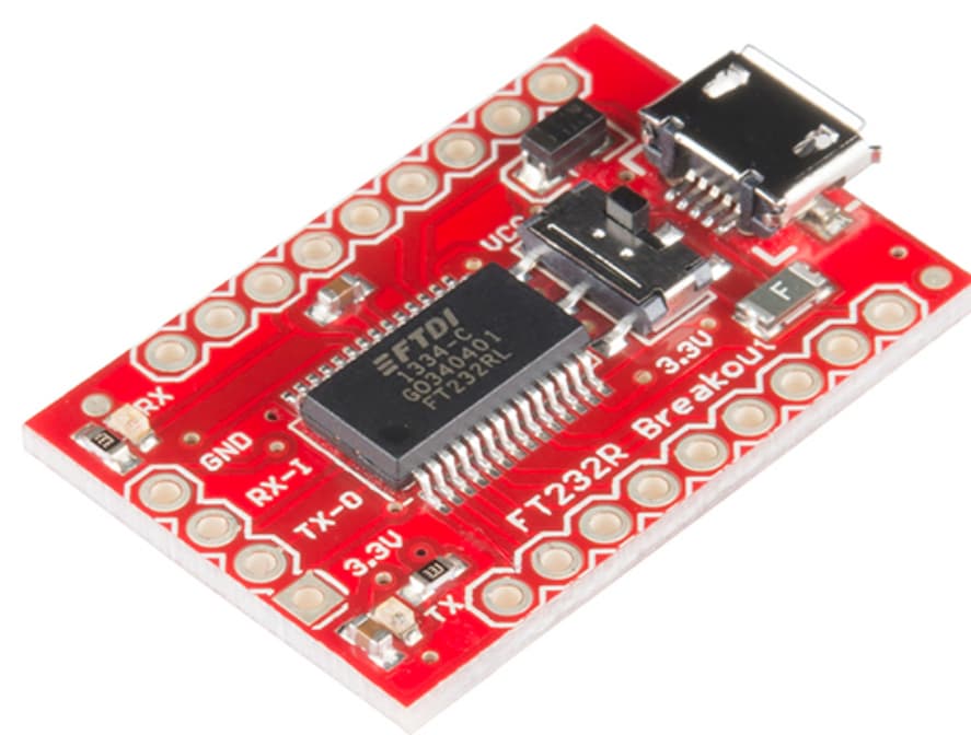
check the FTDI + PC combination with Arduino Serial Console: plug in adapter to USB, connect to port in ArduinoIDE, connect Send and Receive of FTDI, and type on your PC: you should get a good loopback test.

Knowing the FTDI is working well, then go back to your prototype as the issue must be in your circuitry.

Review:
Gammon Forum : Electronics : Microprocessors : How to make an Arduino-compatible minimal board

Hint: if your contracption is oscillating, you should hear the 16MHz harmonics on an old transistor AM radio placed near the uC... just tune from 550KHz up until you hear the "hash." No hash == no oscillation == hardware problem.

When you, apparently successfully, burned a bootloader onto your device, which of the ATmega328P based boards did you select as a target board?
You are aware that if you upload a sketch via a programmer over this ICSP header pins , any existing bootloader is over written ? Maybe reload the bootloader and retry.
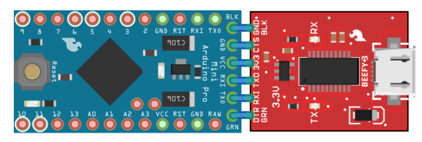
On your next board design, it's best to use a standard pinout for the FTDI adapter.

This topic was automatically closed 180 days after the last reply. New replies are no longer allowed.