DM556Y + Arduino

Dears,

I am willing to buy 3 DM556y (STEPPERONLINE) and 3 Nema 23 (3Nm torque) to built my own CNC.
This CNC will work on the hard wood and light aluminium of 5 mm.

https://www.amazon.de/-/en/STEPPERONLINE-Stepper-1-7-5-6A-DC20-50V-Engraving/dp/B082287FMN/ref=sr_1_7?dchild=1&keywords=nema+23&pd_rd_r=7df45f61-710d-4f5a-833c-6708a00233bc&pd_rd_w=500tA&pd_rd_wg=hNjOV&pf_rd_p=42a02744-0f3e-4409-ad32-55b2f4db4880&pf_rd_r=Y9XCY0Y3V62WY6C54KEF&qid=1610277267&sr=8-7

My questions are:

  • Is this configuration will work fine with those materials.
  • How can i wire the DM556y to arduino.
  • if the connection is established with the arduino, do i need the GRBL or other systems.

In advance thank you.

Please post the data here. I don't want to be invaded by their cookies.

Dear,

As requested here is the data of this kit:

This CNC kit contains:
*1 x Digital Stepper Motor Driver 1.7-5.6A DC20V~50V for Nema 23, 24, 34 Stepper Motor

  • 1 x E Series Nema 23 Stepper Motor Bipolar 1.8deg 3.0 Nm (425ozin) 4.2A 57x57x113mm 4 Wires

Engine specification:

*Manufacturer part number: 23HE45-4204S
*Number of phases: 2.

  • Step angle: 1.8 deg.
  • Holding torque: 3.0 Nm (425 oz).
    *Current/phase: 4.2 A.
    *Resistance/phase: 0.9 ohms± 10%
    *Inductance: 3.8 mH ± 20% (1KHz)
    *Frame size: 57 x 57 mm
    *Body length: 113 mm.
    *Shaft diameter: Φ10 mm.
    *Shaft length: 24 mm.
    *D-cut shaft length: 20 mm.
  • Number of conductors: 4.
    *Cable length: 500 mm
    *Weight: 1.8 kg

Connection

A+:BLK, A-:GRN, B+:RED, B:BLU

Driver Specification

*Output peak current: 1.7 - 5.6 A (1.2 ~ 4.0 RMS).

  • Input voltage: DC 20 V ~ 50 V.
    *Logic signal current: 7-15mA (Typical 10mA)
    *Pulse input frequency: 0 - 200 kHz
    *Pulse width: 2.5μS
    *Insulation resistance: 500MΩ
    *Cooling: natural cooling or forced cooling
    *Environment: avoid dust, oil mist and corrosive gases.
    *Ambient temperature: 0-65℃
    *Humidity: 40% - 90% RH
    *Operating temperature: 50℃ MAX
    *Storage temperature: -20 - 65 ℃

Kind Regards,

Those things will do fine.
Download the data sheet. You will find PU (pulse), plus and minus, DIR (direction) and M (enable).
Connect the 3 plus terninals to +5 volt and the negatives to controller outputs.
Using G code interfaces to Pc environment unless You want to use Your own C code for each CNC job.

Dear Railroader,

Thank you for your reply.
I am a newbie, so i didnt understand very well what u explained to me.
Can you please confirm to me this picture if its correct?

That looks fine.
V+ and V- is for the power supply. A an B, + and - are the stepper connections. A for one coil and B for the other coil.

Read the plate for SW1 to SW8 and set the swiches for current resp. type of stepping.

Thank you very much it is very clear for me now, but in some videos on youtube they connect DIR+, PUL+ and ENB+ to differents Pins in arduino isn't the correct way?

And i want please to know how to work with GRBL.
For my last project i used Arduino + CNC Shield it was little bit easy for me to configure it (it took me a lot of time to understand it in the first).

Thank you

dich:
Thank you very much it is very clear for me now, but in some videos on youtube they connect DIR+, PUL+ and ENB+ to differents Pins in arduino isn't the correct way?

Yes, that's also possible. It does the same job. I prefer this way, connecting plusses to +5 because the low, the minus from the controller, is a little bit more reliable, more safe. Important is that the small output current flows the proper way through the opto diod.

Make the hardware run. Then proceed thinking about Grbl.

Ok, very fine i will connect them as you showed me.
I am waiting for the delivery, when it's done il will update you.

Thank you very much.

Dears,
Please i need your advise on this :

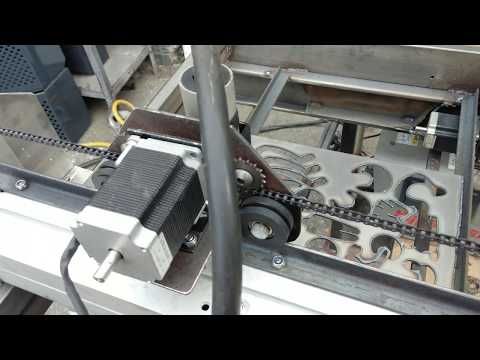
Check out the video from 9:30 to 11:30, is this thing will work for me (Hard wood and 5 to 10 mm aluminium), with the bike chain as transmission (see the image in attach).

This is the configuration that i want to go with, but o read some articles that they didn't appreciate the metal chain.
I think it will work for me but i need you expertise please.

Thank you

CNC Bike Chain2.jpg

CNC Bike Chain.jpg

CNC Bike Chain2.jpg

CNC Bike Chain.jpg

Looks like doable. What kind of objects will be handled? Weight, speed, stability demands, resolution, accurazy etc?

Dear Railroader,

I want to work on the hard wood (beech wood), 10 mm thickness of aluminium or 5 mm.
the speed will not be a problem in the beginning however i need a good accuracy.

I have the feeling that if my machine could handled aluminium of 5mm thinkness it will capable to work on 10 or 20 mm (of course the cnc base should be solid enough to carry this kind of work). am i right?

Take a look at existing builds, rewievs of different ready kits.
Those square bars will not have much rigidity when the carriage is near the middle.
There are "tracks", looking almost like an up side down Y that can be bolted down along the entire length. Using the same construction but using ball bearings at 120 degrees instead of 90 is thinkable unless You buy that track together with a ready carriage.
Working in 5, or 10 aluminium might use hugher forces than one would guess.

This topic was automatically closed 120 days after the last reply. New replies are no longer allowed.