Hello,
I need your help because I feel like I've been overthinking this problem. Maybe you'll spot my mistake.
I cannot send a DMX signal with my Teensy 4.1 card, I receive it very well (reading the monitor and the internal LED of the card).
Do you think the problem comes from the module I'm using or elsewhere ?
Needs
My project must receive DMX data from my card, analyze (algorithm) and write new DMX values out.
I use TeensyDMX library.
#include <TeensyDMX.h>

namespace teensydmx = ::qindesign::teensydmx;

// Pin for enabling or disabling the transmitter.
// This may not be needed for your hardware.
constexpr uint8_t kTXPin = 8; // Teensy 4.1 - TX2 = 8 | RX2 = 7

// Récepteur DMX sur Serial1
teensydmx::Receiver dmxIn{Serial1};

// Create the DMX sender on Serial2.
teensydmx::Sender dmxTx{Serial2};

void setup()
{
  // Turn on the LED, for indicating activity
  pinMode(LED_BUILTIN, OUTPUT);
  digitalWriteFast(LED_BUILTIN, LOW);

  // Set the pin that enables the transmitter; may not be needed
  pinMode(kTXPin, OUTPUT);
  digitalWriteFast(kTXPin, HIGH);

  // Initialize the DMX sender and receiver
  dmxTx.begin();
  dmxIn.begin();
}

void loop()
{
  // Read value
  uint8_t valueDmx = dmxIn.get(1);

  Serial.println(valueDmx);

  if (valueDmx < 50)
  {
    // Switch on
    dmxTx.set(15, 255);
    digitalWrite(LED_BUILTIN, HIGH);
  }
  else
  {
    // Switch off
    dmxTx.set(15, 0);
    digitalWrite(LED_BUILTIN, LOW);
  }
  delay(1);
}
I don't know labeling of your RS485 module, but if you don't have some wiring scheme from Groove, expect that RX goes to RX and TX to TX.
Converter is translator, not a serial communication partner.
Thanks for your answer. I tried plugging the cables into the TX to TX and RX to RX pins, that doesn't work either. In reception mode, this connection works and the webshop writes that the RX and TX are reversed in the manufacturer's data sheet.
Good luck with new board.
Be aware with rx/tx, there's no general rule how converter pins are labeled. So if no documentation, you need to try them both way.
I changed DMX light for my tests and it works!
This means that the signal will not be interpreted by all the devices.
The device in question that doesn't work is a 12v led dimmer (DMX Decoder 512 4CH x 8A, LED Controller) that I use to control headlights for stage (music band).
Here is my new test code :
#include <TeensyDMX.h>

namespace teensydmx = ::qindesign::teensydmx;

const unsigned int channelIn = 65;  // channel input test
const unsigned int channelOut = 1;  // channel output test

// DMX receiver on Serial1
teensydmx::Receiver dmxIn{ Serial1 };

// Create the DMX sender on Serial2.
teensydmx::Sender dmxTx{ Serial2 };

void setup() {

  Serial.begin(115200);
  Serial.print("Receive and send test");

  while (!Serial2 && millis() < 4000) {
    // Wait for serial port initialization
  }

  // Turn on the LED, for indicating activity
  pinMode(LED_BUILTIN, OUTPUT);
  digitalWrite(LED_BUILTIN, LOW);

  // Initialize the DMX sender and receiver
  dmxTx.begin();
  dmxIn.begin();
}

void loop() {
  // Read value
  uint8_t valueDmx = dmxIn.get(channelIn);

  Serial.println(valueDmx);

  if (valueDmx < 50) {

    // Switch on
    dmxTx.set(channelOut, 255);
    digitalWrite(LED_BUILTIN, HIGH);

  } else {
    // Switch off
    dmxTx.set(channelOut, 0);
    digitalWrite(LED_BUILTIN, LOW);
  }

  delay(1);
}
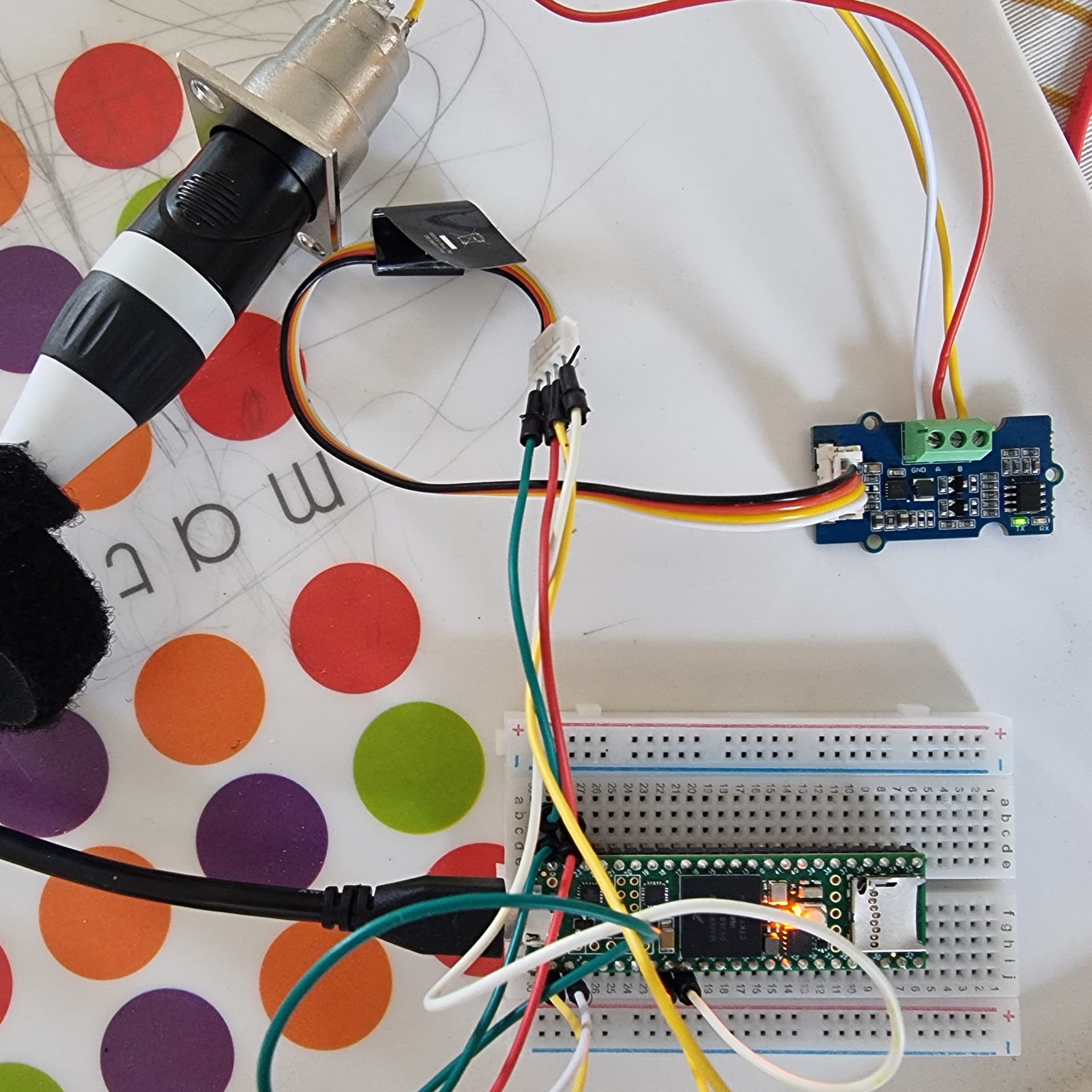
Here's the connection for the sending module :
Module Grove RS485
Wire Jumper colors
I/O Teensy 4.1
GND
Black
GND
VCC
Red
3.3v
RX
White
7 (RX2)
TX
Yellow
8 (TX2)
I'm waiting for the new module to see if it will be recognized by more devices. I think my decoder is more sensitive to voltage levels (< 3.3volt).
I wanted to correct a mistake I made in my previous message regarding the wiring. During the transition from the prototype to a cleaner version with soldering, I realized that I had used two different types of cable (a Grove cable and another similar one) whose yellow and white wires were reversed.
To avoid any confusion, here are the correct wiring tables: