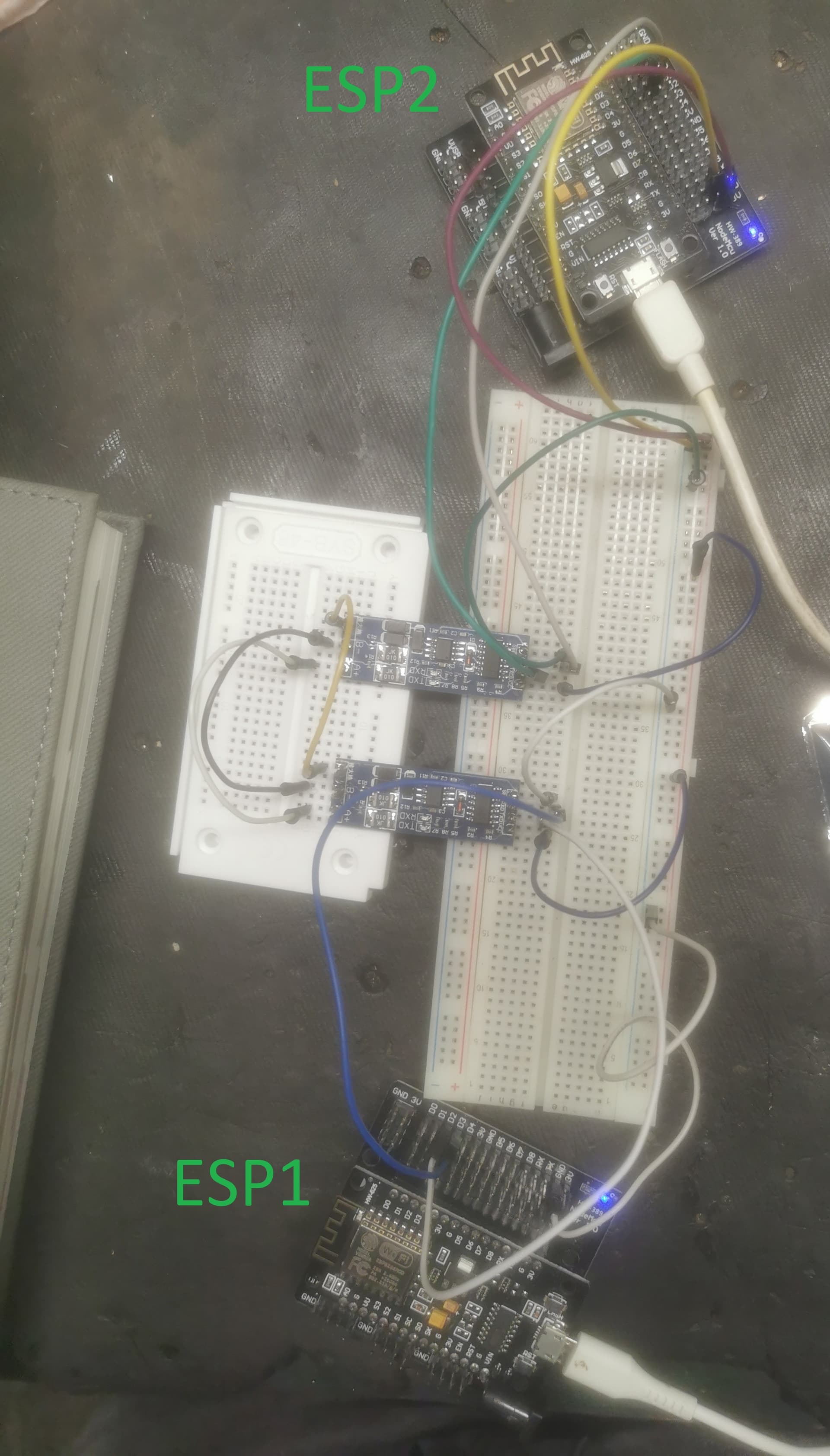
I’m completely new to the Arduino/ESP world. I have two ESP8266 NodeMCU boards and two MAX485 modules. I wanted to connect them together via MAX485.
During my tests, sending data from ESP1 to ESP2 worked fine. Then I tried sending data from ESP2 to ESP1, and that’s where I ran into a problem. ESP2 seems to be sending data (the TX LED on the module lights up), but unfortunately ESP1 doesn’t receive anything (the RX LED on the second module doesn’t light up).
I have no idea what could be causing this one-way communication issue. Swapping the modules around doesn’t help. I also tested a loopback between RX and TX on ESP1, and the data was sent and received correctly.
I seem to remember the MAX485 uses 5V logic - the ESP8266 uses 3.3V logic - you may have damaged the ESP8266
consider using a module such as the sp3485
are you using EspSoftwareSerial? - what baudrate are you using? software serial fails at high baud rates
consider switching to a microcontroller with spare hardware serial ports such as ESP32 - it makes connecting serial devices much simpler
I use 9600 baudrate, also module with Max485, I bought have information that they can run on 3.3V so that why i bought them. I don’t know why i can send from 1 to 2 but not from 2 to 1. Sadly i don’t have esp32 to test it now.
Edit:When my receiver(RX and TX pins) are disconnected RX LED of module blinking with TX LED of second module.
'If' you are going to use swSerial, you should use espsoftwareserial
On the other hand you should probably just use hwSerial, if needed on the swap pins.
If the MAX485 is powered with 5v as it should be then yes. The nodeMCU Rx-pin (gpio 3) usually has a diode and pullup resistor on it though, but keep in mind that is the only pin that may have this feature. The ESP8266 pins are not 5v tolerant. If you do have a voltage divider on that particular RX pin, that may be affected by that setup though.
How about you post a full schematic and a link to the devices used.
Also please inform us why you want to use a MAX485 transmission. A simple wired connection (with a current limiting resistor in line for safety) may suffice for what you want to achieve in the end and greatly simplify your project.
I need an ESP to communicate with my furnace controller (via RS485) in order to collect information from it and display that data over the network (the ESP is perfect for this). Since I don’t have much experience with ESP or the RS485 protocol, I wanted to practice in a safe environment, so I decided to train using two ESPs. However, I ran into a problem — I can only send data in one direction, and I have no idea how to fix it.
if you are using the modules pictured in post 7 they are based on the SP3485 transceiver which which can be powered from 3.3V and use 3.3V logic which should be suitable for the ESP8266
These are exactly the ones I’m using, and they theoretically work (I can send data from ESP1 to ESP2), so they do work to some extent. However, I still have no idea why, when I swap sides, ESP1 doesn’t receive any data.
well these modules are not full-duplex, but only half-duplex. Which pin are you using to switch the direction and where ia it connected.
Yes in most cases really. That said, there are versions of the ESP8266 devboard around that may not have (although all of mine do) These boards are not manufactured by espressif. Espressif doesn't manufacture boards at all.
I came to this conclusion when face with the issue of not getting a decent RX signal on GPIO 3 when running 5v logic through a voltage divider. (whereas when using the swap() pins it was all working perfectly) In fact i just wasn't getting a HIGH or a LOW signal at all (can't remember which it was) Got the DMM out and started measuring on the pin and found the pullup (to 3.3v) and then located the diode.
The test is obviously simple. Create a voltage divider and connect it to 5v. and check the results through digitalRead(), but remember to change the pinMode for gpio 3 to INPUT after starting the Serial port, because the ESP8266 has a different pinMode for all functions.
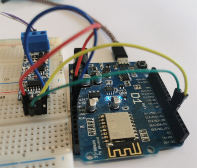
have a look at this which runs on a ESP8266 WeMos D1 transmitting/receiving data over RS485 from a Nano
using ESP32 core 3.3.0 and EspSoftwareSerial
// ESP8266 RS485 using SP3485 RS485 transceiver and SoftwareSerial pin D5 GPIO14 Rx and pin  D6 GPIO12 Tx
//  https://www.maxlinear.com/product/interface/serial-transceivers/rs-485-rs-422/sp3485
// set Tools/Board NodeMCU 1.0 (ESP-12 Module) or Generic ESP8266 module

// NOTE: load EspSoftwareSerial from https://docs.arduino.cc/libraries/espsoftwareserial/
#include <SoftwareSerial.h>

// SP3485 module VCC to ESP8266 3.3V
// ESP8266 pin Rx GPIO14 (D5) to RS485 RO
// ESP8266 pin  x GPIO12 (D6) to RS485 DI
SoftwareSerial RS485Serial(14, 12);  // D5 and D6

// RS485 DE and RE to ESP8266 pin D7
// NOTE not used on this specific SP3485 module - automatically switches Tx/Rx
#define DE_RE 13  //D7  //RS485 Direction control DE and RE jumpered together

#define RS485Transmit HIGH
#define RS485Receive LOW

void setup() {
  while (!Serial)
    ;
  delay(1000);
  // Start the built-in serial port, probably to Serial Monitor
  Serial.begin(115200);
  Serial.println("\n\nESP8266 to RS485 using SP3485 module\n - Use Serial Monitor, type in upper window, ENTER");
  pinMode(DE_RE, OUTPUT);
  digitalWrite(DE_RE, RS485Receive);  // Disable RS485 Transmit
  RS485Serial.begin(9600);            //Initialize software serial with baudrate of 115200
}

// loop sending data from Mega to RS485 and receiving data
void loop() {
  // read characaters from Serial Monitor transmit over RS485
  if (Serial.available()) {              // Arduino Serial data avaliable?
    digitalWrite(DE_RE, RS485Transmit);  // Enable RS485 Transmit
    RS485Serial.write(Serial.read());    // Send byte to Remote Arduino
    RS485Serial.flush();                 // wait for byte to be transmitted
    digitalWrite(DE_RE, RS485Receive);   // Disable RS485 Transmit
  }
  // read characaters from RS485 display on serial monitor
  if (RS485Serial.available())         // RS485 serial data available?
    Serial.write(RS485Serial.read());  // read character and display it
}
esp8266 displays
ESP8266 to RS485 using SP3485 module
 - Use Serial Monitor, type in upper window, ENTER
hello from nano
test2 from nano 1234567890
Nano displays
Nano to RS485 - Use Serial Monitor, type in upper window, ENTER
Use Serial Monitor, type in upper window, ENTER
hello from ESP8266
test2 from ESP8266
test3 from ESP8266 1234567890
Thank you for your involvement in the topic and for the code. Unfortunately, I have to go to work now, so I will test it tomorrow and let you know what result I got.
forgot about the photo!
you appear have lots of multiple connections
also I have had problems with the plugin ESP8266 NodeMCU GPIO Boards in your photo giving poor connections
although not perfect I prefer the white solderless breadboards shown in post 15 - but keep interconnections to a minimum and wires as short as possible
in the end I use soldered custom PCBs in particular in industrial applications