I'm making a simple circuit that receives DMX signal to control a relay but also passes the DMX signal on to a normal DMX controleld light.
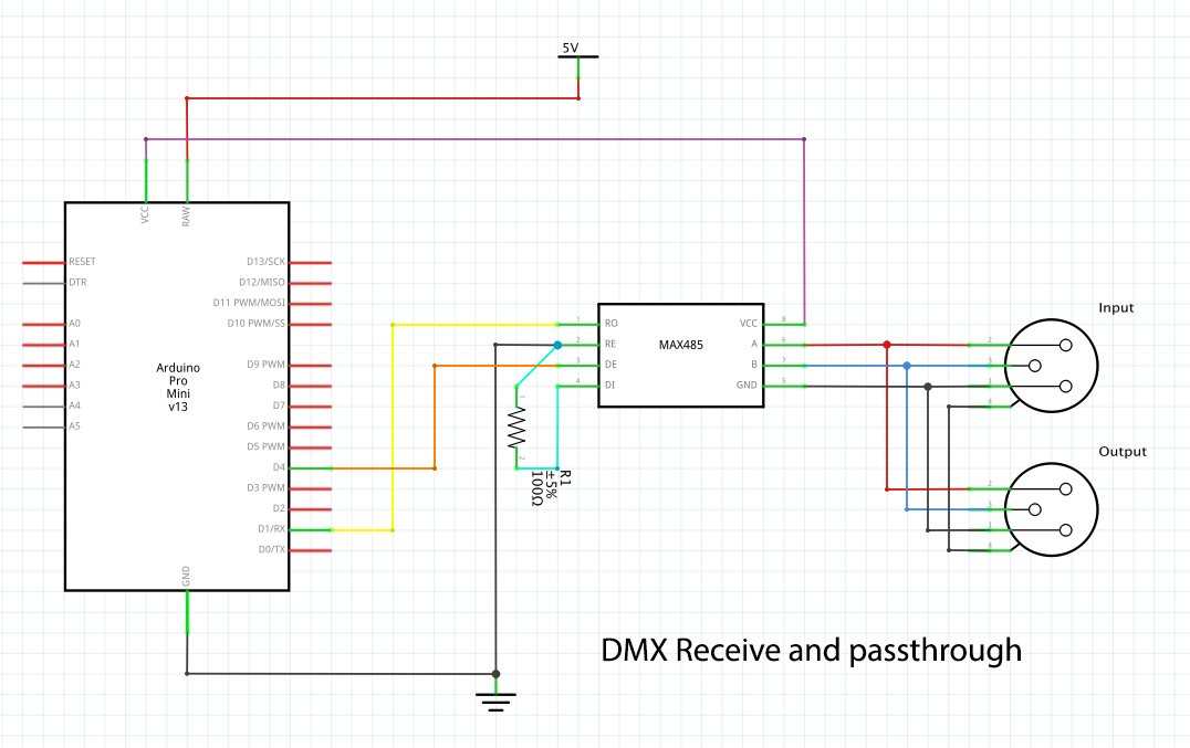
I have simply connected the XLR input to the XLR output (as suggested in this link).
It now receives and controls the relay just fine, but when I connect the next DMX device (the light) to its output neither of them receive any DMX signal. When I power off the Arduino circuit then the next DMX device gets its DMX signal just fine.
Do I need to isolate the circuit somehow? Any ideas why this is happening?
In my interpretation of that circuit you connect DE of the MAX485 (or similar chip) to Vcc directly. This enables the output driver constantly which blocks the whole bus.
But as far as I can see there is not activate of the RE pin, so it's interesting that you can receive any information at all. It might be that the pin is floating and it often enables the reception but that's never reliable.
yes the DE pin gets +5v directly from the powersupply (red cable) and the RE pin is connected to the RX pin on the Arduino. It is interrupted by a small switch so I can easily disable the chip to program the Arduino, so it might be a bit hard to see in the picture.
yes the DE pin gets +5v directly from the powersupply (red cable) and the RE pin is connected to the RX pin on the Arduino.
In this case I doubt that this can work. The pin RO should be connected to the Arduino RX pin and RE should be either connected to the pin driving DE or directly to GND.
As I wrote: DE connected to 5V blocks the complete bus. This pin must be driven by the Arduino and only set HIGH if you send out data. In all other cases this pins must be LOW. Your sketch has to take care for that. A cheap (and not very reliable) solution is to connect DE to DI, in which case the driver is only active to transmit 1s but I don't know if DMX allows for that (must have a defined bus state to 0).
It is interrupted by a small switch so I can easily disable the chip to program the Arduino, so it might be a bit hard to see in the picture.
Please draw a wiring diagram (or even better, a schematic) of the complete setup. There might be other hardware errors in it.
The diagrams I was following were obviously wrong. I'll make a schematic and upload it here in case anyone else has this problem so they can see it clearly.
It is recommended to use a so called "Terminator" on the output of the last node in the DMX chain to prevent reflections of the signal. It is made by soldering a 120 ohm resistor between pins 2 and 3 of the last XLR output, usually done on a plug that you can just place at the end node as needed:
The connection from DE to D4 doesn't make sense to me. In your code you don't use D4 for anything. You need such a connection only if you plan to send anything but then you need a connection from DI to TX.
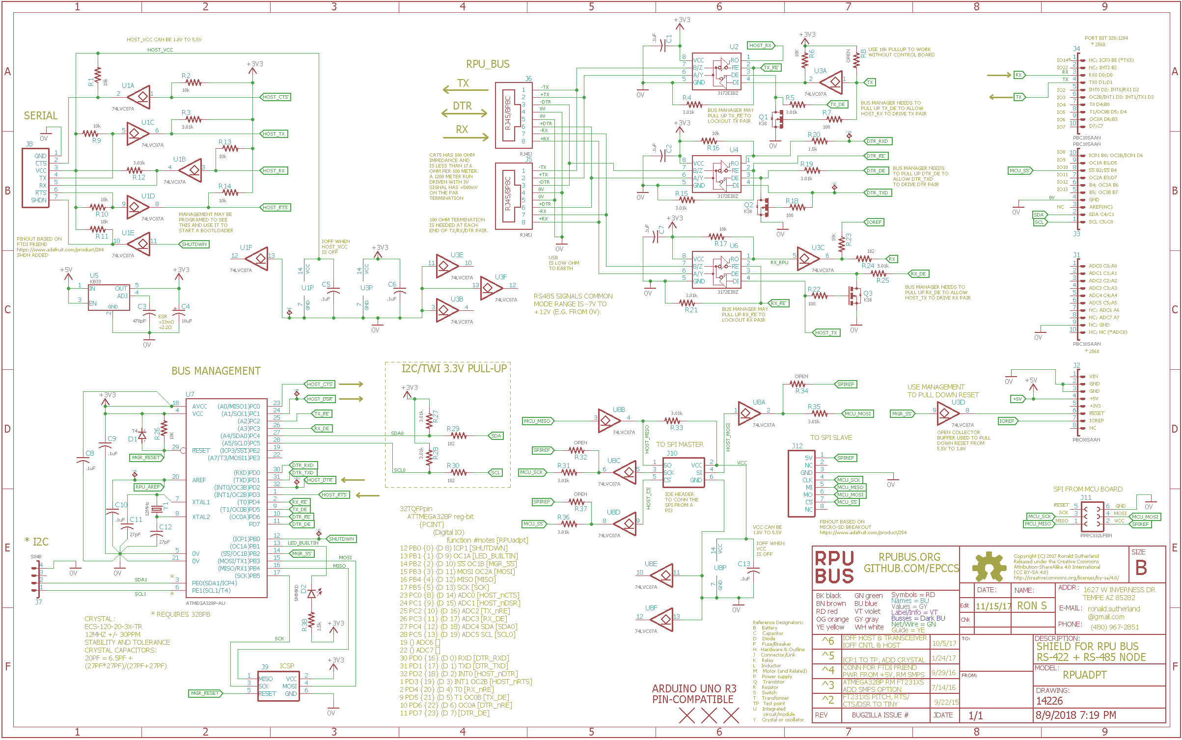
The idea was originally from a DMX circuit someplace, I think it was also on one of Sparkfun's boards. U6 is the part you will want to look at it is set up to receive without needing push-to-talk signals from the controller.
I end up using three transceiver's per board because I want a way to bootload multiple selected targets (with available unmodified tools), but if you don't need that then one should do.
There are three manufacturers with transceivers that should work (ISL3172, MAX3085, and THVD1500) for this sort of link. I recommend one of them even if you set up an old-school RS485 link.