Hello every one, I need your help. A few months ago I bought an arduino starter kit in cooking-hacks and in this kit there was a NTC sensor included. The problem is, i did the code in order to measure the temperature but when i measure the output resistances through serial monitor I see the resistance increasing and this is the normal behaviour of PTC sensor. So I don´t know if the sensor i have is wrong or i´ve done de code badly.
This is my code:
#include <stdio.h>
#include <math.h>

int ntc=A2;
float vout;
float vin=5;
float beta=3950;   //Coeficiente formula SteinHart-Hart, dada en el datasheet
float Raux=3000;
float Rinf=0.0;
float Rout=0.0;
float R25=28000;//Resistencia dada en datasheet a 25 grados
float T25=293.15;//Temperatura kelvin a 25 grados
float TempK=0.0;
float TempC=0.0;


  void setup() {

    pinMode(ntc, INPUT);

    Rinf=R25*exp(-beta/T25);

    Serial.begin(9600);


  }


  void loop() {

   vout=((vin*analogRead(ntc))/1024);
   Rout=(R25*vout/(vin-vout));

   TempK=(beta/log(Rout/Rinf));
   TempC=TempK-273.15;

   Serial.print(TempC);
   Serial.print(" C (");
   Serial.print(TempK);
   Serial.println(" K)");

   delay(2000);

}
can you post the schematic?
Have you tried to swap the fixed resistor and the NTC? I assume they form a voltage divider, and if swapped the behaviour is different
Thanks robtillart for your response and sorry for my late answer. I´ve swapped the resistance with the sensor as you said and you was right, now the temperature in the serial monitor increase if I touch the sensor with my fingers, but now the problem is that there is a great difference in temperature between the 2 dispositions.
In the first one i could measure 22 degrees inside a room and with the new one I measure 18 degrees in the same conditions. Is this normal?
Sorry, but i´m using a mac and i haven´t found an easy application to draw a schematic
Sorry, but i´m using a mac and i haven´t found an easy application to draw a schematic
pencil paper phone?
As the voltages my not be exact you might have a difference, so you should callibrate the code to match the real voltages (e.g 4.95) and the exact value of the resistors (e.g 9.89K iso 10K).
I changed the ntc sensor and now i´ve got a 10 k ntc sensor from vishay. Now this is my code:
#include <stdio.h>
#include <math.h>

int ntc=A0;
float vout=0;
float vin=5.03;

float beta=3977;   //Coeficiente formula SteinHart-Hart, dada en el datasheet
float Raux=9250;
float Rinf=0.0;
float Rout=0.0;
float R25=9200;//Resistencia dada en datasheet a 25 grados
float T25=293.15;//Temperatura kelvin a 25 grados
float TempK=0.0;
float TempC=0.0;

float RT0=23950; //Resistencia a 0ºC
float RT100=1433; //Resistencia a 100ªC
float T0=273;
float T100=373;

  void setup() {

    pinMode(ntc, INPUT);


    Serial.begin(9600);


  }


  void loop() {

   //beta=(log(RT0/RT100))/((1/T0)-(1/T100));
   Rinf=R25*exp(-beta/T25);


   vout=vin*((float)(analogRead(ntc))/1024);
   //Serial.println(vout);
   Rout=(Raux*vout/(vin-vout));
   //Serial.println(Rout);

   TempK=(beta/log(Rout/Rinf));
   TempC=TempK-273.15;


  Serial.println(TempC);
   delay(2000);

}
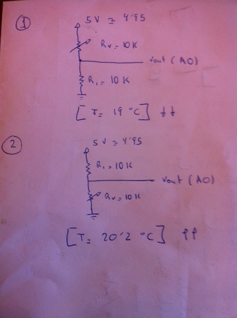
I took a photo with my phone hahaha and this is both circuit possibilities:
As you can see in the code i measured with a multimeter the different values of the different resistances and i added to the code.
In the first circuit shown in the photo, i measure 19ºC inside a room and as i said before if i touch with my finger the sensor the temperature displays in the monitor serial decrease.
In the second circuit, i measure about 20ºC and the value increase if I heat the resistance(logical behavior).
The second drawing would be the correct circuit but the thing is that I think inside this room would be at least 23 degrees, so i don´t understand these discrepancies
Solved!!!
Robtilaart thank you very much for helping me. The mistake was the temperature bad defined at 25º, i didn´t notice. Now the sensor measures about 25 degrees.
The voltage was bad in the drawing, the real voltage is 5.03 v.