Hello everyone,
I'm currently designing a PCB drone with the 8520 brushed motors an Arduino.
However, I wonder whether a gate driver is necessary for my Mosfets?
I will control the motors with 20khz PWM. Does anyone know whether I can switch quickly and efficiently enough with my gate current?
(VCC is of course a 1S HV Lipo)
Reduce the 1K gate resistor in accord with the maximum current draw allowable for the port pin. The 10K resistor should be connected between the port pin and GND, not the gate.
That is an interesting question about the border line case between needing a purpose made mosfet driver and not needing one.
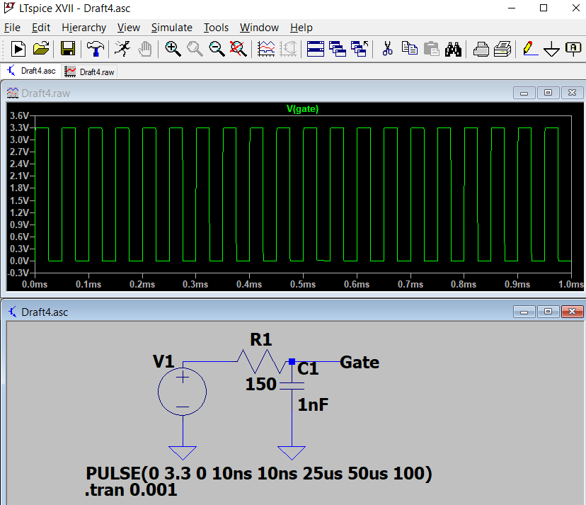
The mosfet in this case is a logic level with Rds(on) of 32mOhms @ 2.5 volts and an input capacitance of around 1nF.
You are driving the gate with a ( push pull ) Arduino pin via a, say, 150R resistor and with PWM at 20kHz
My approach would not be very scientific. I’d do a simulation in LTSPICE to model the RC network at that frequency and visually estimate, from the wave form, the the % of the time the mosfet would be only partially conducting.
If that looks OK, and the device is otherwise within the specified parameters, I’d simply do a test to see if the mosfet gets hot under the anticipated load conditions.
I have seen some mosfet circuits where there is a (fast) diode across the gate resistor to speed the discharge of the gate, presumably on the basis that although an Arduino pin needs a current limiting resistor to charge the gate, it doesn’t need one to discharge it.
Hello, everyone,
I thank you for the valuable tips and assistance. I appreciate that.
I have revised my circuit. I already apologize if this is completely wrong. Is this design better? This time I connected a P Channel Mosfet in front of it. I want to be on the save side, so I decided to use a mosfet driver, at least in case one can call this approche a driver
A Arduino Uno can charge and discharge the gate with 40mA.
Now the discharge of the gate is with a 10k resistor ? That is super slow.
Which Arduino board do you use ?
Mosfet drivers exist for a reason. You can try to find a schematic of induction cooker. Those use high frequencies and the mosfets probably don't have a capacitance of almost 1nF.
Did you know that there is a trick to make a Arduino Uno charge and discharge a mosfet gate with 400mA ? That will break the Uno, but 200mA is possible. It is done by changing the output pins of a whole port at once and connecting all those pins together.
Hallo Koepel,
I am slowly realizing that my schematic is not that well thought out. I'll think about it again for the next few days.
I read that the MIC4416 is one way to solve this problem.
Nevertheless, I would like to work on my schematic a little more to find out whether this is also possible with a single p-channel. I have the feeling that I still have a lot to learn from these lines of thought. On the other hand, it also helps others if I or we come to a solution. In the worst case, I just take a driver module. After all, they are not there without a reason, yes
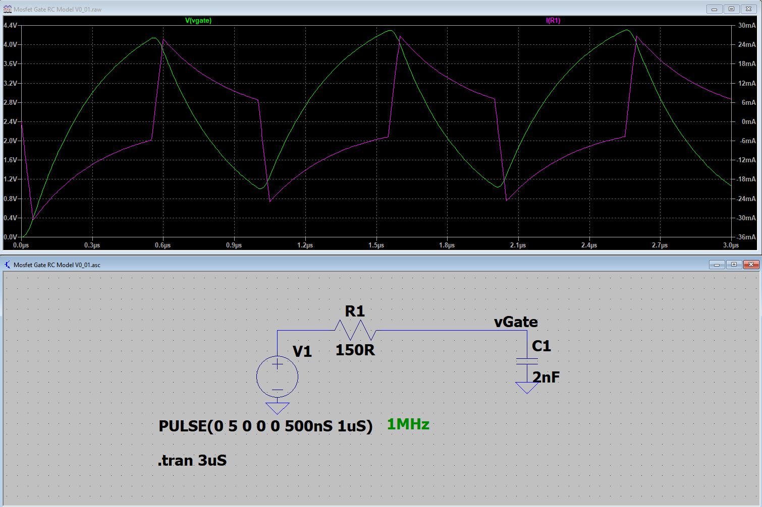
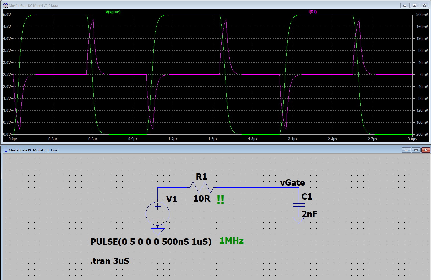
That looks quite conclusive. Out of curiosity, I repeated the experiment to see where it would break. That is where it is clear that an Arduino pin could not be used. At 1MHz and a gate capacitance of 2nF it looks quite grim and the Mosfet may not even switch off. Of course, this assumes that Pulse is a reasonable model of the Arduino pin.
The Schottky diode can be a normal diode. This one is only 40V and it has leakage.
The 1N4007 is considered to be "slow", but in this situation the 1N4007 is really fast !
I hope you don't mind, but may I say that this circuit seems to be a political statement
The Nano can push and pull 40mA, so you have choosen 50mA with the 100Ω resistor when VCC is 5V.
When the first P-channel mosfet is on, then 50mA is wasted for no good reason
I don't know how noisy the motor is. Perhaps a capacitor or a RC snubber circuit over the motor is needed.
Thank you Koepel! I'm sorry, I should have said that I didn't apply my last question to a nano. Thanks to you, I now understand that I don't need a driver.
Nevertheless, I was still wondering whether the design would be possible with just one P-Channel as a driver. I took 100Ω so that the mosfet can be turned off quickly. I can also use 200Ω there
I have now heard from several that the 1N4007 is too slow. Why is it suddenly fast? And what do you mean with leakage?
The circuit will work. Since the 10k is connected to VCC, it is not possible to drive a 12V motor with a 3.3V or 5V Arduino board.
A Schottky diode has leakage current with a reverse voltage. It depends on the temperature.
In a high frequency circuit, the 1N4007 is slow.
For example with a low energy signal of 100kHz, then the 1N4007 has capacitance and recovery time and will eat energy from the signal. The diode might get hot and the signal might be less strong.
However, as a flyback diode next to a motor, it is very fast. It can very easily take that pulse from the motor. That pulse from the motor is strong enough to overcome the capacitance and recovery time. With the low PWM frequency of the Arduino, it won't get hot at all.
I'm sorry that I don't know how to explain it better, I don't know all the details. In the past I also thought that the 1N4007 was slow.
There is a path from VCC to "M1" via the 10k resistor. Therefor VCC may not be much higher than the voltage of the Arduino board.
When you use 3.8V power for the motor and a Arduino Uno running at 5V, then I know what to say. When it can be anything, then I don't know anymore.
A Lipo batter is not 3.8V, it is 3.0 ... 4.2V.
A normal transistor can also drive a mosfet gate. When you use a NPN transistor for the first stage, then you don't need the 10k to VCC in the circuit.
Sometimes a mosfet is better (less forward voltage drop, less heat), sometimes a transistor is better, and there are also IGBT transistors for the real stuff.
The 20kHz could warm up the 1N4007. Sorry for the confusion, I forgot that you were using 20kHz. You can put your finger on it, so see if it gets a little warmer. In this case, a Schottky diode also a good choice.
The first one is uncertain.
The 1S Lipo voltage may change, and the 3.3V is fixed. After a reset or power on, the pins of an Arduino are high impedance and the 3.3V could not be there yet.
During startup and during runtime, no one can tell what the p-channel mosfet will do.
The second one has the 10k resistor to charge the gate to a positive voltage. That is very slow.