In which case you measure it with the resistance setting on your DMM ( Digital Multimeter ).
Interesting one. I think the TIP120 is popular for probably the same reason the IRF5x0 series remains popular - some people started using it, wrote about it, and now everybody thinks they need one.
Unfortunately, you clearly do not know what a "flyback diode" - or by whatever other name it is called, does. It is not the case that "just sticking a diode somewhere" addresses the problem. 
This posting may help, but you also need to read this discussion where I have explained some major problems people, even otherwise experienced engineers, have in understanding it. 
And just to really confuse you even more, in an "H-bridge", that diode in each of the four FETs actually is the "flyback diode"! 
A great advantage of bipolar transistors (and Darlingtons) is their interchangeability. You need only to match (or exceed) current and voltage rating of the original part and you have a good chance the circuit will work.
With MOSFET you can get better performance if you know what you are doing. But there are hundreds of MOSFETs and there is little chance to have (or be able to source easily) exactly the same part as the random guy from internet and there are much more characteristics that may be important: Gate voltage for turn on, on resistance, Gate capacitance etc.
When you do a beginner set you may add a TIP120 and hope it will work in nearly any circuit that wants a Darlington. I don't think there is a "universal MOSFET."
When you do a tutorial you use a Darlington because when a noob uses another it should work too. Using MOSFET will screw the noob.
Thanks for the pointers. Good info, as I am just working on the design of a solenoid driver for an RC engine. I'll ask my questions in the other thread.
A diode across the switching device is of no use if you are simply using one transistor to switch the load. The diode needs to be across the load. However in a half-bridge or full bridge the diodes on one device protect the partner device, as in MOSFET H-bridges where the body diodes preclude any necessity for free-wheel diodes (not true for one MOSFET driving a load as stated above).
@anon35827816 and everyone in the chat, here is the schematic for the circuit of mine, sorry it took so long.
Thanks in advance.
Dean.
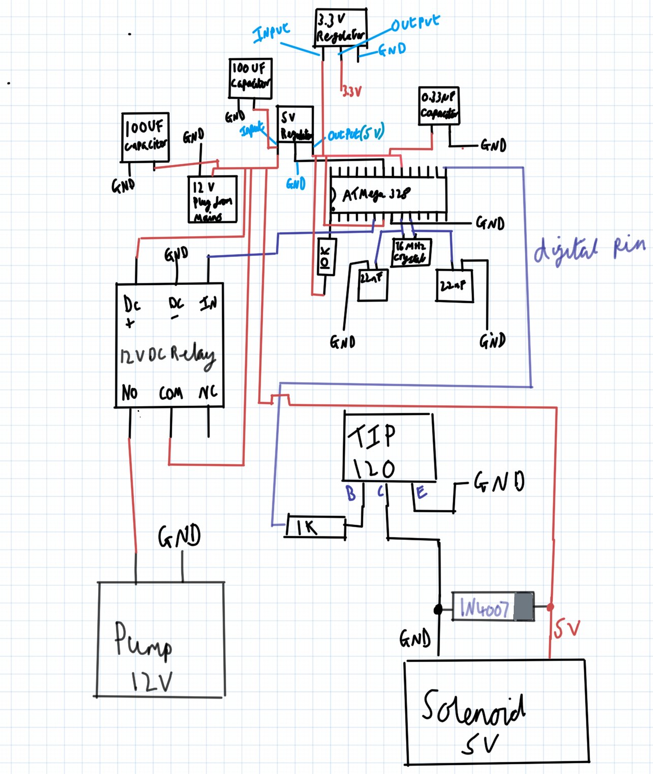
Edit: forgot to add the attachment sorry
Where?
It's an issue only if the duty cycle is excessive. Running a solenoid with a higher voltage pulse makes it operate much faster. Needs a cooling off period after each pulse.
Paul
The 12V from your mains supply seems to be connected to your 5V lines.
What is the current capacity of this supply?
Are you taking the measurements with the pump turned on? The way you have it that pump could produce severe interference, you have a relay but are bypassing the isolation it affords because you need the 12V to power the rest of your circuits.
The capacitors on the output of those regulators should be of the ceramic type. Often a larger electrolytic type is wired in parallel with a small ceramic type. I would put a 0.1uF ceramic capacitor on each power pin of the processor, as close to the pin as possible.
Have you done that coil resistance measurement yet?
It looks to me that your problem is power supply related.
Not according to your diagram.
In addition to the 5V/12V mishap around the solenoid, there's some more odd stuff going on.
The solenoid is shown as connected to GND, as is the emitter of the TIP120, so that would mean the TIP120 does effectively diddly squat.
The ATMega328P seems to have 2x 22nF around its crystal - I'm surprised it starts at all this way given those caps are 1000 bigger than they should be.
I don't see the point in having 2x100uF on the 12V rail.
There's a 3V3 regulator that supplies...thin air? with 3V3.
All considered I get the feeling the schematic we're looking at may not be the circuit as it's built. Perhaps some photos of the actual device might help...?
I used PAINT to move things around a bit.
RED for 12v, purple for 5V
green and black for ground
looks like caps for the 5v regulator need to be added.
looks like the 3V3 is not connected ? it would also need caps.
if the relay is a relay module, you might want to add a resistor on the digital line.
I "FIXED" the errant 5volts to the solenoid, but OP needs to verify.

I must say that using a "bare" ATmega328 really is "doing it the hard way", making things more difficult and potentially introducing many minor problems. 
If you use a Pro Mini (clone) it is cheaper, you have properly configured bypass capacitors, crystal or resonator clock, reset circuitry and a convenient indicator in a reliable form.
It is worth to learn to use bare chip. What if the ready-made solution does not fit? Wrong form factor, you want another crystal (20 MHz; or watch crystal for ultra low power consumption), another supply voltage etc.
One of my ESP8266 modules failed after about 2 months of operation - one of the decoupling ceramics decided to turn into a jumper. It may be only a bad luck but is really "properly configured bypassing" from an unknown Chinese vendor guarantee of a worry-free operation?
We are still waiting for the OP to measure the coil’s resistance. Without that we are all just p****** in the dark.
How is your collection of whips and leatherware in the basement going? 