Introduction:
The topic of flyback diodes came up in another thread (in which I had been trying to find out the specific reasons why the conventional wisdom is to not power a DC motor from Arduino 5V PIN — like this, for example).
@PerryBebbington had pointed to this tutorial, and suggested that oscilloscope measurements may yield some insight into the inductive voltage spikes that are generated when switching off a brushed DC motor.
I was interested in exploring the extent to which inductive voltage spikes originating in a small hobby motor could damage an Arduino microprocessor or a MOSFET used as a switch, so I went ahead and performed some experiments, the results of which are reported here.
Methods & Materials:
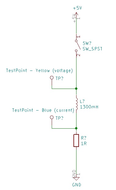
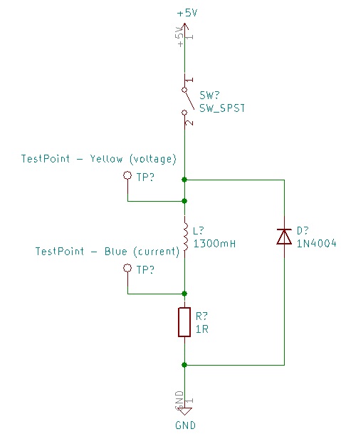
The test circuit is shown below (no MOSFETs or Arduinos were harmed in these experiments!).
The motor used was a Dagu DG01D brushed DC motor. The motor datasheet claims a no-load current of 190 mA and a maximum rated current of 250 mA; ammeter measurements showed that the actual no-load current was closer to 80 mA, and the stall current was approximately 800 mA. The terminal resistance was on the order of 5 Ω.
The switch was a momentary push-button switch. The diode (a 1N5819G Schottky) was removed from the circuit for half of the test conditions, as described below. The power source was a 3×AA (Li/FeS2) battery pack.
Testing consisted of running the motor for a few seconds (by closing the push-button switch), and then opening the switch by releasing the push-button. Each test was performed twice, with the diode either removed or present. In the oscilloscope screenshots that follow, Channel 1 is generally the lower trace (annotated with red labels), while Channel 2 is generally the upper trace (annotated with blue labels).
Results for Time Base 100 ms/div:
Nothing too untoward, but a bit unexpected that the pushbutton switch takes almost 700 ms to fully disengage when released. My best guess is that this is due to mechanical bounce, and not arcing (as it is also observed with the flyback diode in place). The feared inductive spikes are nowhere to be seen — but this is an illusion due to aliasing in the digital oscilloscope. We'll zoom in (by a factor of 20,000×) to get a better view...
Results for Time Base 5 µs/div:
Here, we do see the voltage spike across the switch, when it is opened in the absence of a flyback diode. The switch voltage in this trace peaked at around 16V, but the peak height was variable from trial to trial (although generally on the order 15–20V). I was relieved not to see a 300-V spike, as I had feared based on @PerryBebbington's results above. Without the flyback diode, the initial voltage spike lasted about 10 µs, and there appeared to be some damped oscillation at a frequency on the order 60 kHz. As expected, when the flyback diode is introduced, the voltage across the switch is reduced to something on the order of the supply voltage (5V).
What about the effects of motor inductance on the power source? With or without a diode, there is nothing there that resembles the voltage spike that is experienced by the switch. Nonetheless, we do see some kind of fast spike right when the switch is initially opened, and this spike seems to be present both with and without the flyback diode. Let's zoom in further (by a factor of 100×)...
Results for Time Base 50 ns/div:
Now it gets interesting (and confusing!). Those initial fast spikes seen in the previous set of traces were evidently manifestations of transient oscillatory responses, which appear to have major frequency components on the order of 10 MHz and 100 MHz, respectively. The presence or absence of the diode seemed to mostly affect the frequency content of these voltage traces, while the peak height seemed relatively unaffected by the diode when it came to the voltage acting on the power source — and only slightly reduced when it came to the voltage across the switch. Per the 1N5819G datasheet, "rectification efficiency measurements show that operation will be satisfactory up to several megahertz", so >10 MHz is likely a frequency range in which the Schottky diode is ineffective due to its parasitic capacitance (which is on the order of 100 pF).
Overall, the presence of various oscillatory behaviors indicates that capacitative effects in the system are important on short time scales, and that this is the case both with and without the diode. The rotor's angular momentum, when coupled to the circuit (via back-EMF and magnetic torque generation), is expected to act as an effective capacitor. Beyond that, I imagine that some parasitic capacitance (perhaps in the switch or in the leads) is emerging as a dominant component when the switch first opens, as the in-rush of charge from the motor inductor must get stored somewhere.
Discussion and Conclusions:
You decide....


