Will I need a flyback diode?
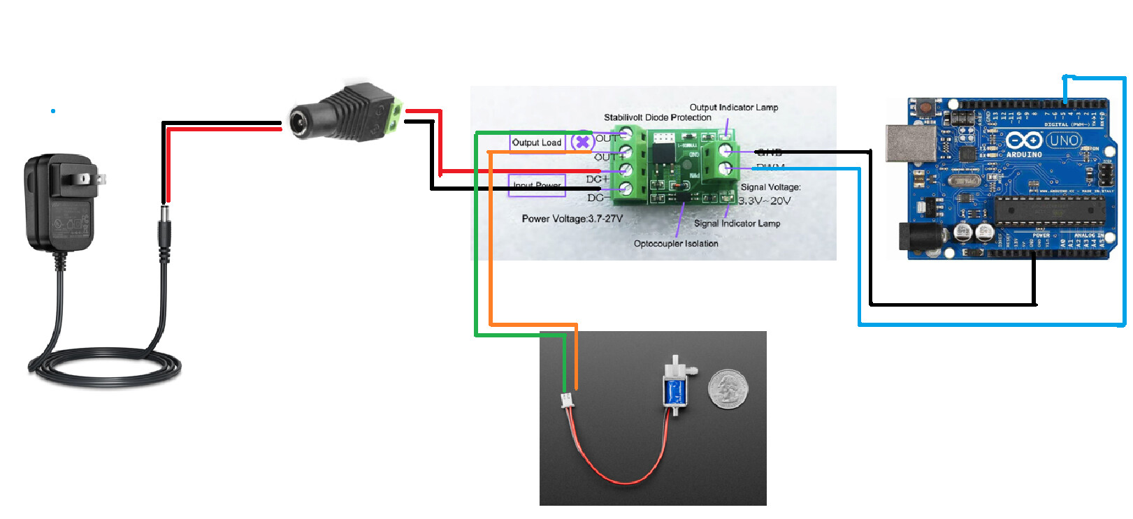
My goal here is to control the solenoid valve through the arduino
Hi, @ekn-ard
Welcome to the forum.
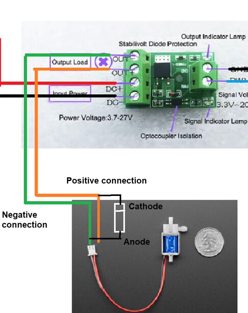
As the switch module has a MOSFET on it, it would be advisable to add a back EMF diode across the solenoid coil.
Tom.... ![]()
![]()
![]()
![]()
Thank you. Just to be absolutely sure, I will place the diode (1N40007) on the positive wire of the solenoid valve. Yes?
Hi, @ekn-ard
The cathode of the diode, the end with the white ring, goes to the positive connection of the solenoid.
The other end, the anode goes to the negative connection of the solenoid.
This makes the diode reverse biased when you operate solenoid and forward biased for any back EMF.
Tom.... ![]()
![]()
![]()
![]()
Solenoids don't care about + and -. Only care about the current that makes the magnetism that moves the armature that does the work.
Yup, but if @ekn-ard is just using it to switch ON and OFF, not PWM it will be fine.
"PWM" I would think is from @ekn-ard cutting and pasting, instead of drawing a schematic.
Tom.... ![]()
![]()
![]()
![]()
Is the board meant specifically to drive relays? If so, it may already have a flyback diode on it, although no harm in having a diode across the coil as suggested in prior replies.
Keep in mind that mosfets often fail shorting so your valve could remain opened when it should not be.
During normal on-time the diode is reverse-biased and does nothing. The moment the MOSFET opens, the coil reverses its polarity; the diode becomes forward-biased and carries the same current that had been flowing through the MOSFET, now through a closed loop consisting of the inductor and the diode. This keeps the MOSFET’s VDS down to about 1 V and lets the current (and the magnetic field) decay safely.
Bottom line: A diode wired between source and drain doesn’t protect the MOSFET from the inductive kick; the fly-back diode must be wired in anti-parallel with the inductor, not with the transistor.
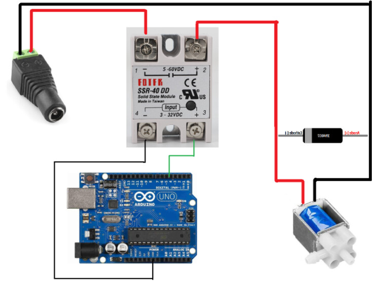
I'll keep this in mind. But then what do you suggest I use to control a solenoid valve thru a microcontroller? An SSR-DD perhaps?
DC-DC SSR and optoisolated mosfet module are technically pretty much same thing.
Both can be designed and built well or not so well.
If you already have mosfet module, just add flyback diode and give it a try.
According to the provided link
About D4 : The square black diode is probably a 1N4148WT. It is marked "T4". This fly-back diode protects the other components against reverse voltage spikes due to an inductive load.
While the image says an SSR-40DD, I plan to use an SSR-25DD to control a 6v solenoid valve
Which is better to use if I want to control a 6v solenoid valve? An F5305s MOSFET module or an SSR-DD? I have both. What's the best relay if I want to actuate a solenoid valve?
The relay would be the easiest to build with. Your circuit looks good and you correctly picked a DC solid state relay, Good Job!
It should work ok but it seems like an expensive component to use for such a simple task. A simple MOSFET or other transistor would be much smaller and cheaper.
What is the spec of the solenoid valve? (Other than being 6V) What is it's coil resistance?
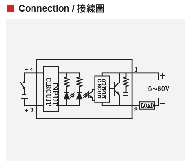
Going by the label on the SSR, you have got the output wiring wrong.
You have got the positive wire from the power socket going to pin1 that is labeled '-'.
However there is a drawing in the Fotek SSR-25DD manual that shows pin 1 as being positive.
I'm not sure which is correct.
Good catch. Just to be safe, I will try to put on the left side just like what the SSR states.