I spent a day trying to get the I2S to work on my Arduino nano ESP32-S3. I'm using the standard Arduino Esp32 Boards BSP. The examples in the Arduino IDE don't work. I went to the Arduino API documentation at:
The documentation doesn't match the library. I looked at the source code and verified this. I was able to piece together code based on the documentation, examples, and source code. It seemed to work as far as dma was firing and calling the callbacks (onI2SReceive and onI2Transmit), but no data was being digitized (ADC or DAC). I could see the clock signal on the designated pin. But no data on dIn or dOut pins. I proved the pins themselves work by manually sending and receiving data using analogRead() and analogWrite().
@kander123 So that is the 'official' long winded name for boards?
I hope he knows there is no need to mention it in the additional URL's anymore, it's part of the IDE install now and has been for a while. Adding one that is not 'official' might cause problems!
Exactly what examples were tried and how did they not work? Since I just tried one and it compiles, I will put my money on a wiring error. Or is it a Boards 3 situation? I do see the following in the migration doc.
I'm new to Arduino. I'm not familiar with the terminology. BSP is what the rest of the world calls the Tools->boards software. "Sketches" is also a new term for me. It sounds like a close cousin of "App". I've just been calling it a program for the last 45 years.
I apologize for my ignorance. I'm still learning the architecture. I thought I2S worked directly with the ESP32 internal ADC. I see I need an external board that does the digitization?
My application just needs to digitize an analog audio signal. Originally, I was going to use analogRead in a timer interrupt, but I thought I could get a less jittery digitization using I2S. Not the case?
The question now is, do I stick with using a timer interrupt or do I buy an audio AD shield? My audio signal is the output of a voice synthesis chip. It doesn't need a pre-amp like a microphone as the Vpp is on the order of a couple volts. You could drive a speaker directly if you wanted to. I just need something that does ADC at audio frequencies and rates.
The end goal is to live stream the audio over ethernet. Can anybody recommend an ADC? Am I best sticking with a timer interrupt?
I just looked at what is available on Amazon. Almost all the ADCs are I2C. There is one I2S that looks good, but the inputs are either RCA or 3.5mm jack. I'm taking a signal straight of a chip pin. I'd prefer to go straight to the ADC, rather than route it to a jack, through a cable, through another jack. I could probably desolder the 3.5mm connector of the ADC board and put a header on it. The problem with that is I'm the world's worst solderer and would stand about a 50 percent chance of wrecking the board
Can you post an annotated schematic showing exactly how you have wired this project, but sure to include links to technical information on each of the hardware items. I looked up your ESP32-S3, this is what I found:
The actual ESP32-S3 silicon is one thing, but it is sold in many different module and board configurations.
For example, common ESP32-S3 modules include:
ESP32-S3-WROOM-1
ESP32-S3-WROOM-1U (external antenna connector)
ESP32-S3-WROOM-2
ESP32-S3-WROVER
ESP32-S3-MINI
ESP32-S3-PICO-1
Then each module comes in multiple memory versions such as:
N4 = 4MB Flash
N8 = 8MB Flash
N16 = 16MB Flash
R2 = 2MB PSRAM
R8 = 8MB PSRAM
For example:
ESP32-S3-WROOM-1-N16R8
means:
ESP32-S3 processor
WROOM-1 module
16MB Flash
8MB PSRAM
Then on top of that there are hundreds of development boards from different manufacturers:
Espressif DevKit
Arduino Nano ESP32
Seeed XIAO ESP32-S3
LilyGO boards
Waveshare boards
Adafruit Feather ESP32-S3
WeAct boards
ESP32-S3 CAM boards
Display boards with TFT or OLED displays built in
One thing that catches many people is that two boards may both be called "ESP32-S3" but have:
different Flash sizes
different PSRAM sizes
different USB interfaces
different GPIOs brought out
different antennas
different voltage regulators
different pin assignments
which means code that works on one board may need changes on another.
I2S is simply a transmission protocol for encoded audio data. You appear to want the functionality of a codec.
What is the voice synthesiser chip/device you are connecting to ? I've seen some projects for emulating old voice synthesisers using an ESP32.
Anyway, a similar requirement to yours appears here with an answer: Stream audio from ESP32 over WiFi · pschatzmann/arduino-audio-tools · Discussion #1739 · GitHub
Thanks for the link. I brought a 1980 Votrax SC-01 back to life. Now I want to stream its output over ethernet. Everything I've read says I2S is the way to go for something like that. I'm using ethernet rather than wifi because it's more reliable for streaming. The Ethernet shield I'm using is a W5500, which doesn't chew up the nano processor
I know there are a lot of things like this already out there. The SC-01 is very well known. I heard somebody is trying to make a modern version of the chip. Simulating it would be easy enough, but that's not my goal. I want to make a real one available to anybody who wants to play with it on the web. The project is primarily something I personally find interesting, as well as a learning exercise. Besides the chip and the Arduino, I have to figure out how to stream live audio on the internet. That means getting in to web servers, which I currently know nothing about. I've already got the ethernet part working. I can control the chip from my lap top in bed.
Currently I'm in analog mode. The SC-01 output is about 2 Vpp signal, which is good. It also has a 5 volt dc bias, which is bad. I need to bring the dc bias down to 1.5 volt for the nano. I'm not an analog guy. Is the best solution a decoupling capacitor combined with a voltage divider? Or should I use an op amp? Since it's an audio signal, it needs to be a clean solution. Does anybody have an opinion on this?
This application appears to be like a sort of internet radio application and there are a number of ESP32 examples.
I guess that the SC-01 shares a common ground with the ESP32 so you don't want to lose the DC bias with a capacitor because the ADC cannot work with negative voltages but you want to reduce the signal with a voltage divider to keep it somewhere between 0 and around 3 volts. You can then subtract the DC offset from the output delivered by the ADC if required, the calculation depending on the actual values of the resistor divider.
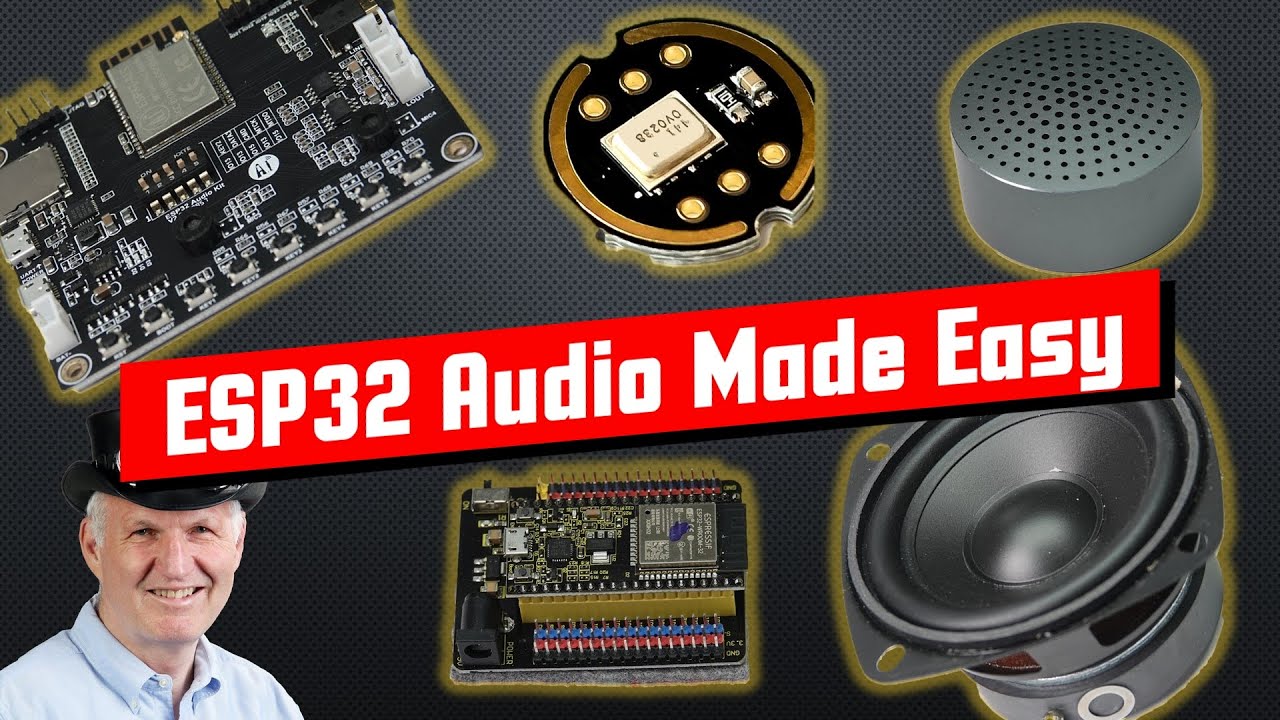
I don't normally recommend videos but this does appear to cover most of the areas you are trying to address:
If you do not know how can we? Check your order, or take a close look at the board? As a last resort you can post a clear close picture of it, somebody may recognize it.