I do understand the JD-VCC issue and the principle of powering it from a different supply so that the Arduino is entirely isolated from the physical relay circuit but what I cannot quite get my head around is whether the configuration below achieves this or not.
System is based in a car. So circa 12V to 14V system, I use a 5V switching regulator linked a row of common +5V screw terminals and a row of common ground screw terminals. Arduino and all other sensors etc on the circuit are powered and grounded on these terminals so no power is drawn directly from the Arduino.
The current circuit is in use and works fine but the relay part of the diagram has not been installed yet.
If I connect from the +5V terminals to JD-VCC and the relay board ground to one of my ground terminals is this "separate" enough from the Arduino that it achieves isolation?
If I were to install an additional switching regulator for another +5V supply they would both eventually share the same ground anyway. I just can't picture how this works. Is the JD-VCC fix normally targeted at people who have connected the +5V and GND pins on the Arduino to the relay. So do all I need to achieve isolation is have ground not sink back via the Arduino so any stray current goes straight to ground rather than through the Arduino so a separate 5V supply are not actually required?
What is the "diff pump?" Current? How often does this cycle on-off? Where is it located in the vehicle?
The usual relays only use about 80mA at 5V. You could use a small linear regulator for the relay board power, and ground the relay near the pump location. Then connect only Arduino +5 to the relay board and relay control to Arduino I/O (Suggest shielded wire). You would not have strict ground isolation, but you would have physical separation. Be careful if you get a single relay board; some are not actually isolated. The 2,4,8 relay boards usually are.
Is that "diff pump" relay the only one?
Yes although I am using a 2 relay board only one relay will be used
What is the "diff pump?" Current? How often does this cycle on-off? Where is it located in the vehicle?
Approx 5A, unpredictable as it cycles due to temp in the rear differential. Probably run for 10 mins off for 5 mins and repeat. Located at rear of vehicle. The relay and controller located at front of vehicle
The usual relays only use about 80mA at 5V. You could use a small linear regulator for the relay board power, and ground the relay near the pump location. Then connect only Arduino +5 to the relay board and relay control to Arduino I/O (Suggest shielded wire). You would not have strict ground isolation, but you would have physical separation. Be careful if you get a single relay board; some are not actually isolated. The 2,4,8 relay boards usually are.
My current regulator is good for 1.5A so can certainly handle the current if I do not need to add another. Its a 2 relay board and definitely has the optoisolator
What kind of vehicle and what's this all about?
Its a racing car and the Arduino currently runs the dash display system. I am adding the relay to control the rear differential oil cooling pump automatically rather than manual flicking a switch like the current setup.
The below is updated to show how I was considering connecting it. 5V supply for both Arduino and the JD-VCC come from the common 5V rail but separately.
Arduino ground is not connection to the relay, the relay ground is connected to the common ground rail and the common ground rail is then grounded to an existing stud on the chassis that a number of other 12V systems already ground on.
My thinking is that as Arduino ground is not connected if there was to be an issued with 12V leaking in to the JD-VCC circuit it would go through the common ground rail and straight back to the battery. It would not cause the Arduino any issues. As the common ground rail is already grounded to a point shared with 12V systems (the external ground in the diagram) then this is effectively the same it is just connecting the grounds together a littler sooner. I could however run the relay ground down to the stud on its own and skip the common ground rail if needed.
So I expect the cooling pump for the rear differential is located in the rear of the body/frame. right?
An objective would be to separate the wiring for the relay and pump motor from the Arduino / Dashboard part. I would suggest mounting the relay back with the pump, keeping that wiring short. The two connections of Arduino 5V and signal to the relay should probably be something like shielded twisted pair wire to avoid picking up electrical noise. The shield would usually be connected only on the Arduino end. Separate 5V wire to relay JD-VCC .
Is there a separate fused 12V (Is this a 12V vehicle?) wire from battery to the relay for the pump? Is the motor negative connection to the frame near the pump?
Consider using a reverse diode across the motor to clamp the reverse voltage spike from turning the motor off.
How close are you to wiring this up to test? Is this making sense??
So I expect the cooling pump for the rear differential is located in the rear of the body/frame. right?
Right
An objective would be to separate the wiring for the relay and pump motor from the Arduino / Dashboard part. I would suggest mounting the relay back with the pump, keeping that wiring short. The two connections of Arduino 5V and signal to the relay should probably be something like shielded twisted pair wire to avoid picking up electrical noise. The shield would usually be connected only on the Arduino end. Separate 5V wire to relay JD-VCC.
At the moment the standard fuse box inc all the original 12V standard car relays for headlights, wipers motors, fuel pump etc is about 6 inches from the enclosure I have the Arduino in and I'm not having any issues with noise so I'm not sure moving the relay all the way back to the pump is needed even if it is best practice.
Is there a separate fused 12V (Is this a 12V vehicle?) wire from battery to the relay for the pump? Is the motor negative connection to the frame near the pump?
Yes relay common is its own 12V fused supply from battery. Battery is in the back of the car so battery negative is connected to the chassis near where the pump is also grounded to chassis.
Consider using a reverse diode across the motor to clamp the reverse voltage spike from turning the motor off.
How close are you to wiring this up to test? Is this making sense??
I was going to wire it up yesterday but mention of reverse diodes, physical relay separation and shielded cable made me doubt I was doing things correctly!
Something that doesn't make sense to me yet still is the separate 5V supplies, whether we are talking about two different regulators or just 2 different wires from the same regulator. I am actually now a little confused as to what we are protecting here by separating VCC and JD-VCC.
Are we protecting against a failure within the relay that causes 12V to leak in to the JD-VCC side of the circuit OR are we protecting against some sort of voltage spikes/noise on the JD-VCC circuit caused by the coil? I assumed the diode on this board was there to prevent any issues the coil would cause so separation was only about keeping 12V away from the Arduino.
If that is the case then I just can't see why I would need two different 5V sources from different regulators. If 12V somehow found its way in to the JD-VCC circuit then it would surely want to continue to ground and so will just flow to the common ground rail then to external ground or directly to external ground if I decide to wire it direct there and skip the common rail. It wouldn't have any interaction with the Arduino as their is no path for it through the Arduino to the car battery?
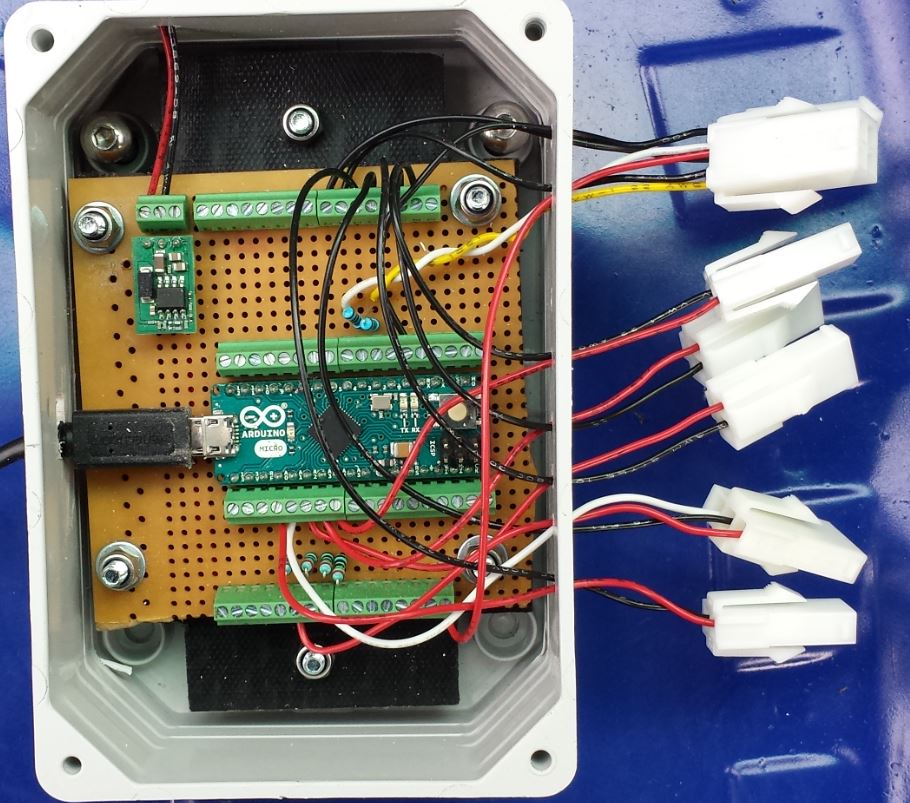
This is effectively how the relay would be wired around the Arduino, in reality the 5V from regulator runs to a row of screw terminals which all supplies come off individually and similar the GND on the regulator runs to a row of screw terminals which all grounds go to individually. Added a photo of it as is to aid understanding.
What you have seems reasonable. The alternative, if absolutely necessary, is to use a DC-DC converter module with isolation betwen power and output.
My concern is switching a 12V 5A motor on and off. That's fundamentally different from the rest of your system.
With the battery mounted near the rear, it seems like a good thing to keep the circuit path of battery-relay-motor-ground as short as possible and away from the Arduino stuff.
When the relay OPENS, the motor will produce a voltage transient of 100 volts or more. I think you need some approach to absorb that. The usual approach, if the motor does not need to be reversed is to mount a diode oriented in the "reverse" direction, similar to the diode shown across the relay coil. I'm not quite sure how to size that diode, but I'd look for a 3A 400+ V rated silicon diode. [Anyone else know how to size that?]
Something that doesn't make sense to me yet still is the separate 5V supplies, whether we are talking about two different regulators or just 2 different wires from the same regulator. I am actually now a little confused as to what we are protecting here by separating VCC and JD-VCC.
You're right in that there will not be complete isolation with the circuit you show. Maybe it's not a problem. But I would personally want the relay close to the battery and motor. At least you can run a separate 5V wire to the relay board, physically separate from the main arduino, stuff.
I suggest you write test code that runs all your gauges etc. but has a switch to force the differential cooler motor on and off, or some timed on-off for a while. Better to test THAT at 0 MPH..
So I think mainly in the interest of better safe than sorry and because I am not 100% I understand what I am doing in this situation I will add a separate 5V regulator and move the relay physically.
I will install the new 5V regulator and relay in an enclosure somewhere between the current Arduino and the pump and I will also run the ground from the regulator and relay to back nearer the pump and battery which is the opposite direction of the Arduino. That will shorten the path and keep it separate from the Arduino circuit as much as is possible. So the shortest and easiest path for any current grounding itself from the relay will be straight back to battery negative connected to the chassis.
I'm concerned about placing the relay right back at the pump for 2 reasons which I think are valid but you may correct me:
Potential voltage drop on the signal wire to operate the relay
I think the longer the signal wire the more potential to pick up noise and cause issues triggering the relay (I would plan to run VCC and IN1 twisted together as I believe this would reduce the affect of this)
EDIT: I forgot to mention, am I right in thinking the D1 diode on the relay board is only for removing the voltage spike from the coil being turned off. So is irrelevant when it comes to dealing with the spike of the pump turning off? I'm curious what affect this will have at the moment, currently I run the pump on a manual switch with no diode so will I simply be arcing the switch all the time and in this case with the relay I will now be arcing between relay contacts?
FURTHER EDIT: After some reading on flyback diode selection I am planning on going for an SR5200 which is good for 5A and 200V. The theory seems to be that the diode must be rated for the same current as is running through the motor but as the current is able to flow back through the diode and does not collapse you do not get such a huge voltage spike and so having a huge voltage rating is not so important however these things are so cheap I may as well go for a high-ish voltage rating.
am I right in thinking the D1 diode on the relay board is only for removing the voltage spike from the coil being turned off.
YES..
currently I run the pump on a manual switch with no diode so will I simply be arcing the switch all the time and in this case with the relay I will now be arcing between relay contacts?
Yes.. I don't know if you can see arcing with the switch you have now (maybe in the dark).. You could (probably should) install the diode now and test with the manual switch..
----( Discussion of the diode rating - Thanks to Paul B )------------------
[Anyone else
know how to size that?]
Yep. It's quite simple.
If the load was a pure inductor (which a motor is absolutely not, the only
inductance involved in a permanent magnet field motor is leakage inductances around
the rotor; the motor is ideally supposed to act as a generator so that on
disconnection, it should have almost the same voltage across it as immediately
beforehand, not an inductive "kickback") then the immediate current through the
diode would be exactly the same as the inductor was drawing, so the rating should be
at least 5 A.
Mind you, this is a current surge and very short-lived, so a lesser rated diode - 3
A as you mentioned - most likely has a perfectly adequate surge rating.
The only voltage the diode ever sees in reverse, is the line voltage of the car.
People do say that you can get impulses of 30 or more volts, so a rating of 50 or
more volts is adequate. It is a diode, so the only voltage it should see in the
forward direction (when it is actually taking the "kickback") is its conduction
voltage of a volt or so. While the voltage transient caused by the leakage
inductance of the motor could be substantial, the conduction of the diode prevents
this rising to more than a volt or so.
-----------------( END COPY )----------------------
There are some 3A rated diodes in a axial package like smaller ones but with heavy leads. Then there are diodes in the TO-220 package (like power transistors) which can have current ratings above 20A.
Do you have any diodes available at the moment? Any old power supplies to cannibalize?
No I don't have anything lying around that I'm will to sacrifice. I'll just have to buy some, very cheap though. I'm away for work just now so I'm not going to get a chance to wire this up for a little while. I might have to do it later in the year as I've got some much higher priority things to get fixed but I feel like I know what I'm doing with it now.