I later would like to replace the IRFZ44N with an IRLZ44N or with an IRLML2502 to drive the MOSFET directly with the Attiny402. ( They are still in the mail so it will take some time.)
Does the circuit and the comments make sense or did I missunderstand something?
I did not power up the system so far since I am not sure if I might damage something.
Should I add a capacitor at the attiny to stabilize the power supply?
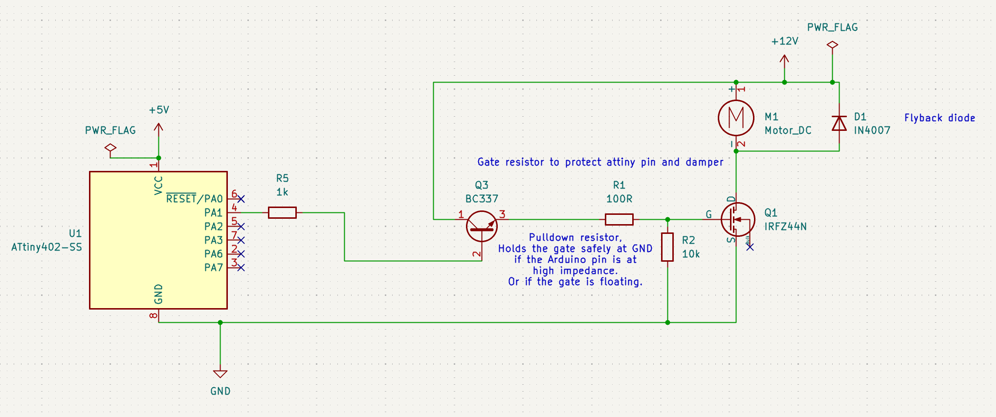
Do I need the 100R if I use a transistor or do I only need that if I drive a mosfet directly with a microcontorller?
(If needed I also can post the code which I use to generate the signal)
I guess the reason is lack of experience it is my first time using a mosfet. I first asked serveral AIs (sadly the schematics are not that useful since there is stuff missing) and with the result I tried to find schematics which I could use a reference. And thats how I created the schematic.
What is the proper way and why (so I can understand it too for the next projects).
Good to know, the idea was to drive the IRLZ44N directly with the microcontroller and a 100R resistor. (The transistor just added so the IRFZ44N would also work). Sadly I still need to wait until it gets delivered. At the moment I am stuck with the IRFZ44N and a box transistors
Yes, the IRFZ44N requires 10V to be fully on so needs the transistor but the IRLZ44N only requires 4.5VDC so can be connected to a 5V logic pin.
HOWEVER both are N chan therefore are used in what is called a LOW SIDE driver. Here is a proper schematic for both LOW side and High side. https://www.gammon.com.au/motors
One good way would be to use Google to look up driving a motor with a MOSFET from a microcontroller. There are any number of examples doing exactly what it is you appear to be trying to do. Ignoring the AI generated drivel at the top of the search results, of course.
Also, doing a search here on driving a motor with a MOSFET produces educational results. A representative sample:
I googled driving a pump with mosfet before, but you are right it is also a motor so that should give me even more and maybe better results? My problem is, that I am not really sure which circuts/schematics are good/safe and which are just "hacked" together. ( E.g. some don´t use a flyback diode )
My first thougth was that I could just use the IRFZ44N but I noticed that I need 10V and that there is another IRLZ44N which does work with 5V. But then there was a post about driving the IRLZ44N with 5V works but it gets really hot. So I tried to find a solution and thought I could add a transistor to get the needed voltage. Thats how the schematic was created.
Here in this post Choosing components for logic level MOSFET motor driver? they use a capacitor to filter the frequence to reduce the noise? Is that correct? So I would make sense to include it too? Does a electrolytic capacitor work or do I need a tantal or ceramic one?
Look more carefully. The MOSFETS are different; the low side is N channel, the high side is P channel. The majority are low-side N-channel because logic-level P-channel MOSFETS are quite rare.
Sorry to say this, but you need to learn to notice ALL the details unless you are OK with smoke and flames.
Sorry, my intention was just to tell the schematics fast apart, I did noticed that there are other differences depending if p or n channeled mosfets are used . Are there other terms like low side and high side driver which are importent to know?
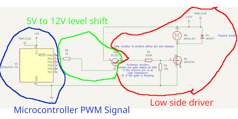
I updated it like this now. Does it now look better? It seems that low side drivers are better for motors at least some one wrote that
Blue: I first use the microcontroller to generate a pwm signal.
Green: Then the transistor is used to shift the voltage above 10V . (only for the IRFZ44N)
Red: With this voltage I am able to satuarte the mosfet (IRFZ44N) to control the motor/pump.
Thank you sonofcy and van_der_decken so far for clearing some things up and the help. It is mutch harder to search for things you don´t know the name as when you got the name
I think you need to learn how MOSFETS work. Then the reason for why/how a Low Side driver using ONLY an N channel MOSFET is done that way.
Right now you are just following the breadcrumbs and taking advice from unknown internet sources that may know nothing. I am attaching a fairly good tutorial beginning on page 9. I hope this helps. 14-fet-transistor-ebook.pdf (1.2 MB)
Wrong. The emitter of that transistor is always 0.7volt lower than it's base.
So 4.3volt max, and even lower because of some volt drop across the base resistor.
Study this page.
Leo..
Aren´t mosfets like electrical switches and depening on the type you got p/n it acts alittle bit different. A n channel blocks the flow if there is no voltage at the gate but if I put a voltage at the gate and it is bigger or equal the threashold voltage then the mosfet let it flow? And the p channel does mirror that behavior with reversed polarities? Thats how they are currently working in my head.
Thank you for your source, I will look into it.
It seems the problem got now "solved". Since I didn´t really found a solution to build it with the IRFZ44N in time so it does not that hot. Now I can wait until the IRLZ44N arrives and the other Mosfet.
Voltage is always relative to an other point.
A fet turns on (starts to) when the voltage between gate and source is higher than it's threshold voltage. Same for N and P-channel, only different polarity.
At the threshold voltage only an insignificant current flows. you can see threshold voltage as a turn-off point.
Above that voltage, the fet acts as a resistor( getting hot with current flow).
Vgs must be significantly higher for the switch to act as a true (low resistance) switch.
That resistance Rds(on) at certain Vgs can be found iin a graph in the datasheet.
Leo..