I am having trouble driving 28byj-48 with A4988. I want it to have more torque since standard-driven 28byj-48 with ULN2003 cannot sometimes start my device and needs a push to start going. I have read that if you remove the red wire from the motor and swap the pink wire with the yellow one it becomes bipolar and can produce more torque. The motor was working fine with ULN2003 but after rewiring and with the A4988 it does not even move.
This is the schematic I have applied:

Arduino nano:
pin 5 to DIR pin on A4988
pin 6 to STEP pin on A4988,
pin 27 to 5v from LM2596
pin 29 to GND from LM2596
A4988 driver ( current was set to 0,15V):
SLEEP 6 and RESET 5 pins bridged together
pin 7 STEP to pin 6 on nano
pin 8 DIR to pin 5 on nano
pin 9 GND to GND from LM2596
pin 10 VDD to 5v from LM2596
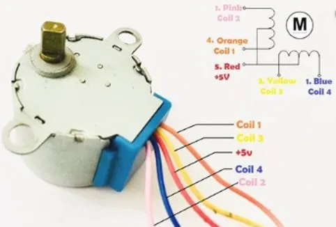
pin 11 1B to orange on 28byj-48
pin 12 1A to pink on 28byj-48
pin 13 2A to yellow on 28byj-48
pin 14 2B to blue on 28byj-48
pin 15 GND to GND from the power supply
pin 16 VMOT to 12v from the power supply
28byj-48
LM2596
This is the code:
#include <Arduino.h>
#include "A4988.h"

#define MOTOR_STEPS 200

#define DIR 5
#define STEP 6


A4988 stepper(MOTOR_STEPS, DIR, STEP);

void setup() {
    stepper.setRPM(120);
    stepper.setMicrostep(2);
}

void loop() {
    stepper.move(1);
    stepper.move(-1);
}
With all of the above motor does not even budge not even a sound.
I will appriciate any suggestions at this point.