Driving 48 selectable LED's over RS485

Hi all, I use the sketch below to read outputs from DCS World (Flight Sim) for 48 discrete LED's and then it will switch the corresponding LED on or off accordingly. It's important to note that the hardware is not set up as an array, each LED is hardwired with a pin to the Arduino Mega, and all LED's share a common ground.

Over USB it works brilliantly, however the intent is to use it with RS485 as experience has shown that using many USB devices slows down the devices so that there is a long lag between actuation and the LED lighting.

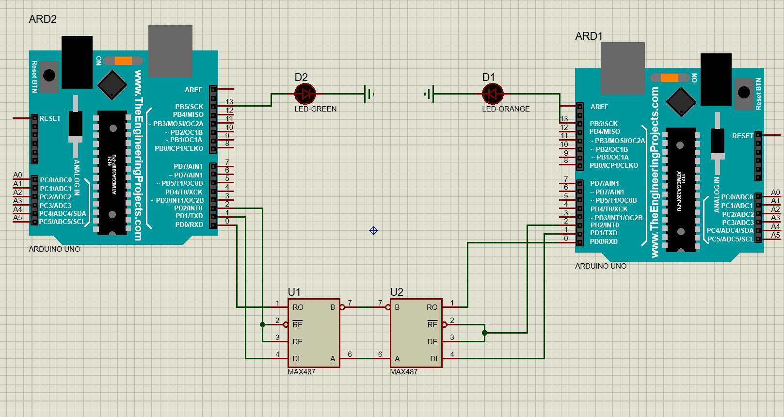
When I change the code over to RS485 and install the MAX487 chip, it seems that something is interfering with the way that the data is being processed, so what happens is that it will only light say half of the correct LED's at any time, and it flickers between the correct ones in banks of LED's

Here is a link to the video I did of the warning light panel working via RS485, after 10 seconds or so you can see the erratic actuation of the LED's

Caution light panel over RS485

Here is the sketch, as you can see it is pretty uncomplicated

//#define DCSBIOS_DEFAULT_SERIAL

#define DCSBIOS_RS485_SLAVE 33

#define TXENABLE_PIN 2
#include <Wire.h>

//#define DCSBIOS_IRQ_SERIAL

#include <DcsBios.h>


//ENG START CYCLEA-10C/CL_A1
DcsBios::LED clA1(0x10d4, 0x0001, 23);
//L-HYD PRESSA-10C/CL_A2
DcsBios::LED clA2(0x10d4, 0x0002, 25);
//R-HYD PRESSA-10C/CL_A3
DcsBios::LED clA3(0x10d4, 0x0004, 27);
//GUN UNSAFEA-10C/CL_A4
DcsBios::LED clA4(0x10d4, 0x0008, 29);
//ANTI-SKIDA-10C/CL_B1
DcsBios::LED clB1(0x10d4, 0x0010, 26);
//L-HYD RESA-10C/CL_B2
DcsBios::LED clB2(0x10d4, 0x0020, 24);
//R-HYD RESA-10C/CL_B3
DcsBios::LED clB3(0x10d4, 0x0040, 22);
//OXY LOWA-10C/CL_B4
DcsBios::LED clB4(0x10d4, 0x0080, 31);
//ELEV DISENGA-10C/CL_C1
DcsBios::LED clC1(0x10d4, 0x0100, 11);
//VOID1A-10C/CL_C2
DcsBios::LED clC2(0x10d4, 0x0200, 10);
//SEAT NOT ARMEDA-10C/CL_C3
DcsBios::LED clC3(0x10d4, 0x0400, 28);
//BLEED AIR LEAKA-10C/CL_C4
DcsBios::LED clC4(0x10d4, 0x0800, 33);
//AIL DISENGA-10C/CL_D1
DcsBios::LED clD1(0x10d4, 0x1000, 12);
//L-AIL TABA-10C/CL_D2
DcsBios::LED clD2(0x10d4, 0x2000, 9);
//R-AIL TABA-10C/CL_D3
DcsBios::LED clD3(0x10d4, 0x4000, 3);
//SERVICE AIR HOTA-10C/CL_D4
DcsBios::LED clD4(0x10d4, 0x8000, 35);
//PITCH SASA-10C/CL_E1
DcsBios::LED clE1(0x10d6, 0x0001, 13);
//L-ENG HOTA-10C/CL_E2
DcsBios::LED clE2(0x10d6, 0x0002, 5);
//R-ENG HOTA-10C/CL_E3
DcsBios::LED clE3(0x10d6, 0x0004, 30);
//WINDSHIELD HOTA-10C/CL_E4
DcsBios::LED clE4(0x10d6, 0x0008, 37);
//YAW SASA-10C/CL_F1
DcsBios::LED clF1(0x10d6, 0x0010, 4);
//L-ENG OIL PRESSA-10C/CL_F2
DcsBios::LED clF2(0x10d6, 0x0020, 6);
//R-ENG OIL PRESSA-10C/CL_F3
DcsBios::LED clF3(0x10d6, 0x0040, 32);
//CICUA-10C/CL_F4
DcsBios::LED clF4(0x10d6, 0x0080, 39);
//GCASA-10C/CL_G1
DcsBios::LED clG1(0x10d6, 0x0100, 38);
//L-MAIN PUMPA-10C/CL_G2
DcsBios::LED clG2(0x10d6, 0x0200, 36);
//R-MAIN PUMPA-10C/CL_G3
DcsBios::LED clG3(0x10d6, 0x0400, 34);
//VOID2A-10C/CL_G4
DcsBios::LED clG4(0x10d6, 0x0800, 41);
//LASTEA-10C/CL_H1
DcsBios::LED clH1(0x10d6, 0x1000, 40);
//L-WING PUMPA-10C/CL_H2
DcsBios::LED clH2(0x10d6, 0x2000, 44);
//R-WING PUMPA-10C/CL_H3
DcsBios::LED clH3(0x10d6, 0x4000, 42);
//HARSA-10C/CL_H4
DcsBios::LED clH4(0x10d6, 0x8000, 43);
//IFF MODE-4A-10C/CL_I1
DcsBios::LED clI1(0x10d8, 0x0001, 58);
//L-MAIN FUEL LOWA-10C/CL_I2
DcsBios::LED clI2(0x10d8, 0x0002, 58);
//R-MAIN FUEL LOWA-10C/CL_I3
DcsBios::LED clI3(0x10d8, 0x0004, 48);
//L-R TKS UNEQUALA-10C/CL_I4
DcsBios::LED clI4(0x10d8, 0x0008, 45);
//EACA-10C/CL_J1
DcsBios::LED clJ1(0x10d8, 0x0010, 59);
//L-FUEL PRESSA-10C/CL_J2
DcsBios::LED clJ2(0x10d8, 0x0020, 57);
//R-FUEL PRESSA-10C/CL_J3
DcsBios::LED clJ3(0x10d8, 0x0040, 50);
//NAVA-10C/CL_J4
DcsBios::LED clJ4(0x10d8, 0x0080, 47);
//STALL SYSA-10C/CL_K1
DcsBios::LED clK1(0x10d8, 0x0100, 7);
//L-CONVA-10C/CL_K2
DcsBios::LED clK2(0x10d8, 0x0200, 8);
//R-CONVA-10C/CL_K3
DcsBios::LED clK3(0x10d8, 0x0400, 46);
//CADCA-10C/CL_K4
DcsBios::LED clK4(0x10d8, 0x0800, 49);
//APU GENA-10C/CL_L1
DcsBios::LED clL1(0x10d8, 0x1000, 61);
//L-GENA-10C/CL_L2
DcsBios::LED clL2(0x10d8, 0x2000, 60);
//R-GENA-10C/CL_L3
DcsBios::LED clL3(0x10d8, 0x4000, 52);
//INST INVA-10C/CL_L4
DcsBios::LED clL4(0x10d8, 0x8000, 51);


void setup() {
  
  DcsBios::setup();
  
}

void loop() {
  DcsBios::loop();
 
}

I suspect that the way RS485 is handling the data is to blame, though I don't profess to be an expert. I can't change the hardware so the only thing I can think of is to somehow multiplex (which I think needs an array to function) or at least make the sketch read the and switch the LED's in a phased or scanned manner, maybe by breaking up the panel into smaller chunks that are read briefly. Maybe read only the first 8 for a couple of milseconds, illuminate them, then the next eight etc...? I hope that makes sense, I'm thinking about it as an engineer

So is there a way to do this?

cheers

Les

I don't understand the DcsBios stuff ( I see that it is a thing that "connects custom-built control panels powered by Arduino microcontroller boards to the flight simulator DCS: World). When I've had a lot of LEDs to drive, I've used the MAX7219 chip, which can drive an 8x8 matrix of LEDs with very few additional components. It connects via SPI.

Hi there, thanks for looking in

The Max7219 chip uses a matrix, and therefore is not workable for this hardware. It would require a complete remanufacture which will be out of the question

cheers

Les

So the problem is the (most probably slow) serial bus interface. There is at least one byte of overhead, the slave address, the rest (baudrate, protocol) is hidden in a black box.

Just a question: how does your PC serve RS-485? By a USB stick?

Then don't use many USB devices with your DCS.

From the working USB connection it's known that it's all a matter of transmission speed. Find a way to speed up the RS-485 transmission, that's the best and IMO only way to improve things.

Hi, @Lesthegringo

Can you please post a schematic of your network?
You do have the terminating resistors connected at each end of the 485 bus?

Thanks.. Tom.. :smiley: :+1: :coffee: :australia:

Thanks for the replies

The RS485 slave is via a max487 chip on a custom made shield for the Mega, hard wired to the LED panel; the master is another Mega with a custom RS485 shield with a MAX487 chip hard wired

As for not using many USB devices, that's going to be tough; there are so many input devices (from memory Joystick, throttle assembly, pedals, five Bodnar BBI-64 boards, USB to 4xHDMI desktop extender, NLR V3 seat mover, 5 inch TFT, Arduino Mega RS485 master) . You need to take a look at the home built cockpits for flight sims, they have tons of input/output devices

I suspect you are right on the transmission speed; Max7219 setups are used in a lot of cases to get over this, but doesn't suit my LED panel

Les

And on that master you run the Flight Sim?

Errr, no - the requirement for resistors has never appeared in any schematic that I have seen for using RS485 with Arduinos; that's not to say that they shouldn't be there, just that it has never appeared as a requirement

For interest's sake at least, why would they be required? It would be simple enough to try it basically I have the setup like this except that the arduino D2 pins go to joined RE and DE pins on the max chips

Just because your LEDs are not in a matrix doesn't mean that they can't electrically be in a matrix. They can be in any physical formation you want.

I think Les is saying that they can't be wired as a matrix because

So he has gone down a design cul-de-sac and is asking for our help to build another road out of the cul-de-sac instead of backing out the way he came in :wink:

I think what you are saying is that using many Arduino, each connected by USB, slows down the PC they are connected to? I've never known that to be a problem, but I've never built a flight sim cockpit.

So your new plan is to have only one Arduino connected by USB, which will act as a controller (notice I didn't say "Master") for many other Arduino acting as peripherals (not "Slaves") over rs485 bus?

If I've got it right, then this is the classic beginner error of thinking that the need for more I/O pins == need for more Arduinos. The better way is to have 1 Arduino (and so only one USB connection to the PC) and extend its I/O pins in one of a number of different ways, and/or reduce the number of I/O pins by using them more efficiently.

That's a fair summary! However it would provide a solution for other devices as well. On the sim rig I have, for example, I currently have the requirement for 47 arduinos. 12 of those nanos are for the engine gauges, one for each. Using USB I can drive all 12 steppers from one Mega, but once you add RS485 into the equation it becomes so jerky and laggy that it is unusable. Even running two steppers from one arduino over RS485 results in choppy movement.

If there was a way to sort of multiplex those it would mean a significant reduction in the number of devices used

Cheers

Les

Right, that's the DCSBios black box. If that software requires a pin number for each LED (see the posted code) then a LED matrix requires a differently configurable Bios.

I admit I only skimmed over that, dismissing it as poorly written and repetitive. But now I see that this library is the reason Les is designing everything in this way, and it's a PITA!

Could it be using software serial? I noticed that pin 33 was used in the sketch originally posted. Can't even find pin 33 on Mega pinout diagrams, but wondering if it is not a hardware UART pin.

Page 7 of MAXIM datasheet.
The reason for the resistors is that the 485 bus is a current bus.

If the examples you saw were breakout modules, the resistors would have already been fitted and had jumpers to switch them in and out.

Tom... :smiley: :+1: :coffee: :australia:

Like I said, it looks pretty easy to incorporate

I have just grabbed an RS485 module from my stocks, and put an ohmmeter across the A and B pins - 120 ohm is what I measure, although I don't know what the internal resistance of the Max chip is

I can certainly add a resistor between the pins, what value would be correct?

Les

It's not pin 33, it's actually reference to slave number 33

cheers

Oh, I see. So what pins does the RS485 module connect to on the Mega?

Can you post the code for the mega that is controlling the rs485 bus?
Is the rs485 bus connected to multiple boards, or just between the two mega boards?

If I found the correct library, looks like it is using the hardware Serial line, but driving it directly:

178   RS485Slave rs485slave(&UDR0, &UCSR0A, &UCSR0B, &UCSR0C, TXENABLE_PIN);
179   ISR(USART0_RX_vect) { rs485slave.rxISR(); }
180   ISR(USART0_TX_vect) { rs485slave.txcISR(); }
181   ISR(USART0_UDRE_vect) { rs485slave.udreISR(); }
182 
183   void setup() {
184     PRR0 &= ~(1<<PRUSART0);
185     UBRR0H = 0;
186     UBRR0L = 3; // 250000 bps
187     UCSR0A = 0;
188     UCSR0C = (1<<UCSZ00) | (1<<UCSZ01);
189     pinMode(TXENABLE_PIN, OUTPUT);
190     //UCSR0B = (1<<RXEN0) | (1<<TXEN0) | (1<<RXCIE0) | (1<<TXCIE0);
191     rs485slave.clear_txen();
192 
193   }