Yeah, that's plausible; if the surface is big enough and there's sufficient airflow, it'll get rid of the 2W of heat alright. If this is bright enough, you don't have to worry about pushing it any further.
Do keep in mind that it's a bad idea to control the LEDs with voltage. As you've determined, a slight variation in voltage results in a big change in current draw. Moreover, this relationship is influenced by temperature, so you can actually get into a positive-feedback loop.
You need to current control the LED with an appropriate driver.
Dimmers? Are you referring to my other thread where I ask how to control the current on the dc-dc? I still don't have a good solution other than a stepper motor to turn the trimpots.
You can use a FET (for efficiency) on a pin to blink the COB slow enough to perceive as flicker.... try 40 ms ON/OFF blink intervals just for starts and maybe shorter ON than OFF to accent the flashing.
Eyes have persistence of vision. If I flash a led 2ms ON, 998ms off, I see that 2ms flash but ON for 998ms and OFF for 2ms slightly dims it. At 40ms frequency, it blends is why try 40ms ON+40ms OFF stutters a bit but not so much. Flight sims in the 90's, 20 FPS was playable.
Power LEDs need a current controlled switching LED driver.
They almost always have a PWM input, to control brightness (and on/off).
Google "sparkfun picobuck" (three in one, but also comes in single,
or Google "3watt led driver" (images) for clones.
Can be (should be) driven directly from the battery.
Leo..
As @Wawa mentions, these are nearly always switching drivers. Mostly buck topology. I usually use MP29894 because it allows use of an external MOSFET and it tolerates up to 60V, which makes it quite flexible. It's also cheap, and takes either a DC or PWM dimming input. Very convenient.
And almost all of the 50 watts is HEAT that must be dissipated into a heat sink. Remember that 50 watts is all created in a microscopic solid state connection. So just because you can touch something without getting burned doesn't mean your LED junction is at the same temperature.
Several years ago my company bid on producing similar LED panels and the LED was attached to the aluminum heat sink with heat conducting epoxy. We never got to actual production with the order.
The COB LED OP has linked to contains more than 300 individual LEDs. A fairly low ~0.15watt per LED means that the chip temperature is not much higher than the temperature of the aluminium heatsink.
Leo..
I've done quite a few high-power LED designs, up to about 350W on a 10x16cm area. Thermal management is the main challenge, for sure. I now limit my designs to ~100W so they fit on an old-school computer processor cooler (the old types used to have larger contact surfaces than the modern ones). Individual 3535 LEDs on aluminium-core PCBs, screw-mounted to the heatsink using generic thermal paste. This works quite well.
Your comment about the temperature of the junction vs. the device is on the money though. Especially in high-power designs with dissipations of >1.5W per led die, this becomes a major challenge. It's quite hard to DIY something that will allow the heat from that tiny surface to dissipate into a large sink.
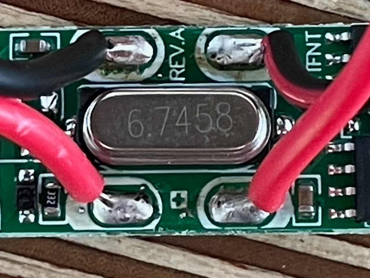
The LEDs are here, attached the pictures of the dimmer. Unfortunately there are no markings at all on the chips. Anyone think there is a realistic chance of hacking into this circuit with an Arduino? As said above I do have a scope if measuring things would be of any help. Thank you all for your support!
The LEDs as can be seen in the last picture are mounted on a 2mm thick aluminium disc. Is this good enough for a heatsink? I have other smaller COB LEDs from this manufacturer that I've been running for hours on my model aircraft, but there they are obviously air cooled.
Maybe. I've peered at the photos a little but I'd have to probe around with a continuity meter to work this out into a schematic. It's theoretically possible to do it with just the photos, but in all honesty, it'll take more time than I'm willing to spend on it.
I did recombine your photos a little, which does suggest a few things:
The IC top right (viewed on the component side) is likely an N-channel MOSFET.
The IC bottom right must be (I suspect) a LED driver although I'm not quite sure how it senses LED current; presumably it's low-side sensing, but I can't make out the traces that would connect that IC in a meaningful way for this purpose. It's a little hard to tell which traces may hide underneath the IC's.
The IC to the left is a small microcontroller/wireless receiver. The antenna for the remote is underneath it (the funny circular thing at the bottom of the PCB). These little chips are often found in devices like these and integrate a very simple (maybe 8051 architecture) microcontroller and a 433MHz (or so) receiver. Btw, 6.7458MHz * 64 is 431.7312 MHz, which seems a little off of 433MHz - perhaps someone with a HAM background could comment on this (@Paul_KD7HB maybe?) Anyway, not a major issue.
The two caps bottom left are probably the oscillator caps; the vertically-oriented caps next to it are probably (?) part of the antenna tuning circuit.
I bet the little SOT23-maked part is something like an MCP1700 that makes the Vcc for the controller from the LED supply.
The bottom diode may play a part in reverse polarity protection (the lower one connecting to the center leg of the 'G1' chip, which is likely the power input to the regulator).
The top diode looks like a 5V zener type so it may play a role protecting a MOSFET gate or a GPIO on the controller (although I'd expect a 3.3V zener for the latter).
One way to hack into this is to cut the connection between the controller and the LED driver IC and apply your own PWM signal to that. If I were to hazard a guess, you'll see a PWM signal if you dim the LED (as intended, with the remote) on the top right pin of the controller.:
And on the side of the supposed LED driver inject your PWM signal. I'd opt for a 3.3V signal as that's probably the logic level on this board.
Be sure to also connect your Arduino GND to this circuit GND, e.g. here:
@rsmls Your post absolutely blows my mind! Thank you so much and for me it's beyond belief how you can figure out so many things by just looking at it. I wish I could do that. As for the logic level and PWM, I'll get out my scope tonight and report back if can see the PWM signal.
Many many thanks, this is awesome help!
As for the AliExpress unit, I'll order it but it might not make it before the race unfortunately.
I'd be thrilled to hear if you observe what I'd expect. Mind you, all of my analysis boils down to a combination of educated guesses with a hefty fudge factor, so take them at face value and verify the parts that are critical to your application.
One concern is that if the controller somehow plays a role in the current limiting of the LEDs, there may be catastrophic consequences to removing its PWM control. So when/if you're going to test this, please do so with a current-limited power supply so you don't inadvertently try the COB LED.
Also, since there's apparently no way to actually limit the LED current in the dimmer, you will absolutely need to use a massive heat sink, regardless!!
Yes, the led driver module will take some time to arrive. You should be able to find similar devices locally, however. In case my scheme falls through, at least you'd have something to fall back on.
I have a 12V 1A wall adapter, will that do as current limiting device? It should probably just brown out if the COB LED pulls to much current?
I have this one this one which can limit current, unfortunately I don't know the range, only the max which is 8A. How would I figure out how far to limit current? Do these multiturn resistors have end stops? Apologies for asking such basic questions.
Your LED should draw about 2A at 12V, which means that it'll brown out by default using that adapter. Not sure if you'll be able to test much with it, since the power supply may either simply switch off, or enter a restart-loop, essentially causing the LED to flicker on and off.
Keep in mind that even at 1A & 12V it will need a heatsink since 12W will be too much for it to run longer than a few seconds or so.
Yeah, might work. In this case the heatsink will need to be much bigger since you're going to drive the LED closer to its maximum dissipation.
The circuit will limit itself; in my experience the pots do appear to keep turning, but in reality they don't change their resistance anymore at the extremes of the range.
After some digging I found a 12V 3A wall adapter. Before turning on the COB LED I mounted it on a big fat piece of aluminum and it works fine. It is insanely bright so for testing I was running it at 25% for which the remote has a button.
I warmed up my scope but unfortunately only got noise on that top right pin (GND on the pad you've marked above). Just to make sure it wasn't oscilloscope user error I grabbed my servo tester and immediately got a lock on the scope and saw pulse widths between 1000 and 2000µs depending on the servo tester setting.
Anything I can help with to find the PWM signal on the dimmer?
That's still underpowered! I don't know how this dimmer will respond to what's essentially a current-starved situation. Maybe the erratic PWM signal you see has to do with this, IDK.
I'd be inclined to test with a power supply that allows the LED to operate at full power. Use a massive heatsink. Then dim to a low duty cycle and monitor the PWM signal.
Alternatively, ignore the fact that the PWM signal is erratic and simply proceed with injecting your own PWM to see if it works.