Hello to everyone,
i am trying to use an DS18B20 to get an temperature measurment.
But i only get an -127 reading.
Through the Forum i learned that this is probably an connection problem.
Is there a problem with the used librarys or is it possible that i fried the sensor?
Or something entirely different...?
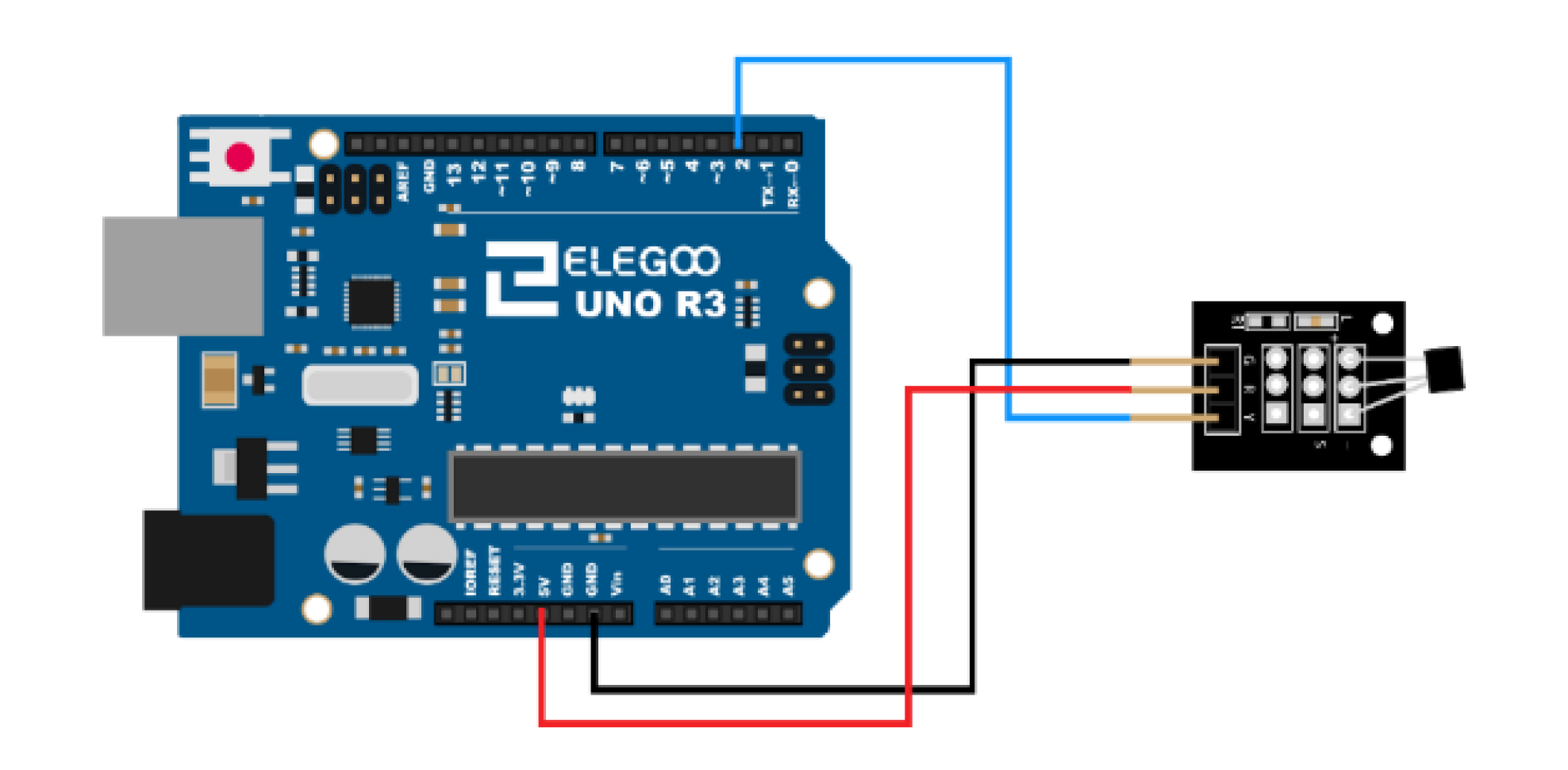
Following is my used Code and the curcuit.
#include <OneWire.h>
#include <DallasTemperature.h>

#define ONE_WIRE_BUS 2

OneWire oneWire(ONE_WIRE_BUS);

DallasTemperature sensors(&oneWire);

void setup(void)
{
    Serial.begin(9600);
  Serial.println("Dallas Temperature IC Control Library Demo");

    sensors.begin();
}

void loop(void)
{

  Serial.print("Requesting temperatures...");
  sensors.requestTemperatures();
  Serial.println("DONE");

  Serial.print("Temperature for the device 1 (index 0) is: ");
  Serial.println(sensors.getTempCByIndex(0));
}
Hi @scout01 ,
Does your module have the resistor between +VCC and the data line?
If not, put a 4K7 resistor.
Post a link with your DS18B20 module.
RV mineirin
Hello,
unfortunately i can only assume at this point.
On the board is a little component which reads 472 with an R1 next to it. This could be the resistor.
The module alone has no link, i got it out of the Sensor Kit from Elegoo.
Hi @scout01 .
First make sure your jumpers are good and that they are wired as per your schematic.
If you have a multimeter, measure the resistance between the OUTPUT pin and the +VCC and see if you find the value equal to or less than 4K7.
If not, then for testing connect a 4K7 resistor between arduino pin 2 and +VCC of arduino.
RV mineirin
-127 simply means "not connected", i.e. bad wiring. The resistor you allude to can hardly be anything other than the 4.7k required and, unless you have abused it, should be just fine.
I have checked my cables and also changed them out to eleminate this posibility.
I only have a pretty cheap old multimeter that couldn't really get an exact reading.
I will try to lend one which is better.
@Nick_Pyner in which way do you mean that i could have abused it?
Another concern of mine is the code.
My lecturer from University said that there could be something wrong with the librarys.
But because the code came with the module, i didn't consider it to be the problem.
I disagree. It might just as well be a current limiting resistor for the smd LED that's right beside it.
@scout01, get a digital multimeter and measure the resistance between pins 2 & 3 on your module (while it's not connected to anything else). If you get a reading that's higher than 4700Ohms or even an out of range value ('infinite' resistance), you need to add a pullup resistor.
//12-bit default resolution; external power supply
#include<OneWire.h>
OneWire ds(2);
byte addr[8];         //to hold 64-bit ROM Codes of DS1
byte data[9];        //buffer to hold data coming from DS18B20
float celsius;

void setup()
{
  Serial.begin(9600);

  ds.reset();
  ds.search(addr);  //collect 64-bit ROM code from sensor
}

void loop()
{
  probe();
  delay(1000);
}

void probe()
{
 //----------------------------
 ds.reset();       //bring 1-Wire into idle state
 ds.select(addr); //slect with DS-1 with address addr1
 ds.write(0x44);    //conversion command
 delay(1000);   //data ready withinh DS18B20 or poll status word
 //---------------------------
 ds.reset();
 ds.select(addr);  //selectimg the desired DS18B20
 ds.write(0xBE);    //Function command to read Scratchpad Memory (9Byte)
 ds.read_bytes(data, 9); //data comes from DS and are saved into buffer data[8]
 //---------------------------------
  int16_t raw = (data[1] << 8) | data[0]; //---data[0] and data[1] contains temperature data : 12-bit resolution-----
  celsius = (float)raw / 16.0;  //12-bit resolution
  Serial.println(celsius);
}
Thanks for all your help and suggestions.
Turns out that the module itself does need the extra pullup resistor.
The existing resistor really is only for the LED above it.
But also i got the oppurtunity to test my code and setup with another module like mine and as i suspected my sensor is simply dead. Probaly from the factory itself because another sensor from the set also turned out to be defect.
With the new sensor my code worked perfectly and immediately sends data.
That means the -127 also could mean that the sensor is broken.
Its common with multidrop busses like the OneWire bus to not include termination or pullup resistors in every module, since termination resistors should only be at the ends of a bus, and there should only be one pullup resistor so that its value is correct - having 12 modules on the same bus each with a 4k7 resistor would give 391 ohms, far too low...
God yes, I should have seen that. .... The idea of having a pullup for every sensor is stupid and should never happen. I guess I was suckered by the resistor value. And what's a LED doing there anyway?