E32 Parameter Setting Problem

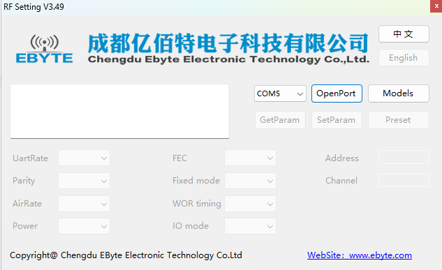
Hello I want to communicate 2 Arduino with E32 433t20d. Only sending basic message with these communication sensors. But the interface of parameter setting of E32 does not worked. I have error ' No response from module'. I use 2 Arduino nano and 2 E32. All wires are done with jumper.
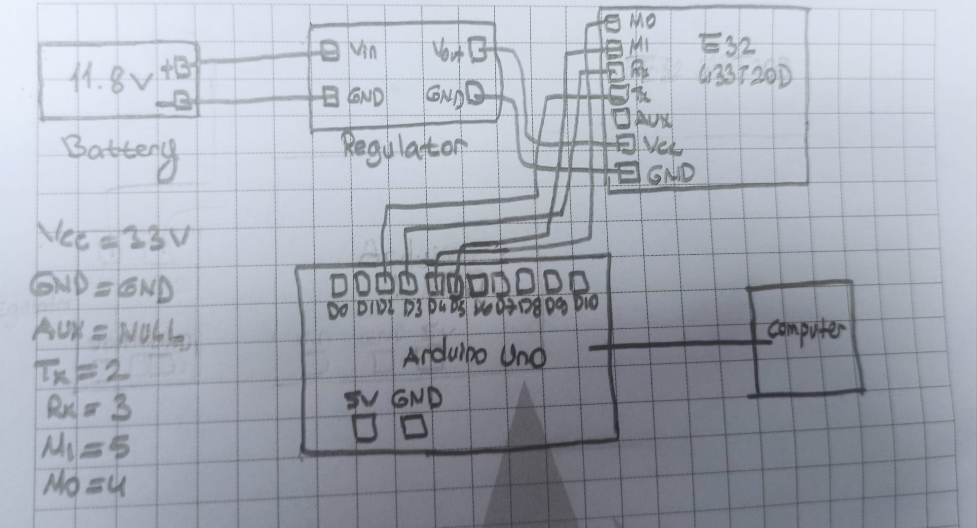
My wiring is:
GND --> GND
VCC --> 3.3V
AUX --> D6
TX --> D10
RX --> D11
M1 --> D5
M0 --> D4

the sender code

#include <SoftwareSerial.h>

SoftwareSerial mySerial(10, 11); //RX, TX

void setup() {
  Serial.begin(9600);
  mySerial.begin(9600);

}

void loop() {
  if (Serial.available()>0) {
    String msg = Serial.readString();
    mySerial.print(msg);
    Serial.println(msg);
  }

}

the receiver code

#include <SoftwareSerial.h>

SoftwareSerial mySerial(10, 11); //RX, TX

void setup() {
  Serial.begin(9600);
  mySerial.begin(9600);

}

void loop() {
  if (Serial.available()>0) {
    String input = mySerial.readString();
    Serial.print("I received: ");
    Serial.println(input);
}

}

And the schematic is here:

and the tutorial: https://www.youtube.com/watch?v=wYjALYK7pqU&ab_channel=JTECH

What is my fault?

Why did you start a topic in the Uncategorised category of the forum ?

Your topic has been moved to a relevant category. Please be careful in future when deciding where to start new topics

does the 3.3V pin provide enough current for your module?

thank you

I searched many tutorial and as far as I see, they used 3.3V

The module may run on 3.3V but what @J-M-L was asking about was how much current the module requires, which is a different thing altogether

Can you measure the voltage on the Arduino 3.3V pin when it is providing power to the module ?

in the receiver you want to check if something arrived on the module so not

but

void loop() {
  if (mySerial.available()>0) {
    String input = mySerial.readString();
    Serial.print("I received: ");
    Serial.println(input);
  }
...

I get it but I also think like him because arduino nano gets very hot.

Before the code I cannot fix RF setting of E32. 'no response from module' provided. This is because of wiring or not enough voltage or current but I checked wiring many times

image

your code specifies pins 10 and 11 for mySerial

SoftwareSerial mySerial(10, 11); //RX, TX

but schematic shows the E32 Tx and RX connected to pins 2 and 3

also recommend you use AltSoftSerial

the Ebyte-E32 manual states the Communication voltage as 3.3V and 5V may damage the device
you need a level converter when connecting to a UNO
I always use 3.3V logic microcontrollers (e.g. ESP32) when connecting to Ebyte devices

have a look at lora-e32-device-for-arduino-esp32-or-esp8266-specs-and-basic-usage-part-1

1 Like

TX RX pins are different wiring according to uno or nano for nano 10 11 used ; for uno 2 3 used

(cf pots 7)

you test if something arrived on Serial rather than the Module's port. So unless you type something in the serial monitor, you'll never go check if a message has arrived

I write some message but the receiver does not receive anything

what mode (M0 and M1) setting do you have the two E32 set too?
for transparent mode (communication between the E32s) the simplest thing is to connect M0 and M1 to 0 (GND)

did you make the modification I gave you?

yes but not worked

post again both codes and post a drawing of your exact circuit (paper + pencil) and power supplies

#include <SoftwareSerial.h>

SoftwareSerial mySerial(10, 11); //RX, TX

void setup() {
  Serial.begin(9600);
  mySerial.begin(9600);

}

void loop() {
  if (mySerial.available()>0) {
    String input = mySerial.readString();
    Serial.print("I received: ");
    Serial.println(input);
}
}
#include <SoftwareSerial.h>

SoftwareSerial mySerial(10, 11); //RX, TX

void setup() {
  Serial.begin(9600);
  mySerial.begin(9600);

}

void loop() {
  if (Serial.available()>0) {
    String msg = Serial.readString();
    mySerial.print(msg);
    Serial.println(msg);
  }

}

one situation is that I connect power supply directly to the E32. the other one is that I connect vcc directly Arduino 3.3V. But I am confused too many example and very different examples

Should you connect GND of the module to Arduino GND?

On page 8 of the manual, it says these cannot be left floating, can be grounded if not used.
In your circuit drawing, you have these plugged in and there's nothing in the code to address them. What are D4 and D5 doing while you run the sketch?

Also, since you're using a 5V Arduino (Nano) with a 3.3V device, the manual also talks about adding 4 10k pullup resistors to the TXD and AUX pins of the module (pg 9) for "some" 5V microcontrollers.