delay(x); means "nothing happens for x ms"
If you are familiar with assembly, it NOPs for x ms.
You have a slower computer. Wokwi shows an approximate speed percentage in the upper-right of the running simulation.
delay(x); means "nothing happens for x ms"
If you are familiar with assembly, it NOPs for x ms.
You have a slower computer. Wokwi shows an approximate speed percentage in the upper-right of the running simulation.
Ah, I thought wokwi was running from a server, didn't realize I was running it. The delay in starting the cycles is actually not a 30 second delay, it's a 1 minute delay. The Serial:print timer is accurate to real time. Just having a bit of trouble actually getting it to print once per second. Not necessary for my purposes, but these kinds of things are small exercises for me to learn. The LEDs start ramping up/down when the Serial.print timer hits 1 minute after the sunrise/sunset is supposed to start, not a big deal at all for the final use, but a bit annoying for testing and I'm still going to try to fix it.
What percent are you seeing? If you shows 50%, the sim will take 2 seconds to execute 1 second of code.
Yeah usually around that. Rather strange that the Serial.print for the RTC actually matches real time though, I hope that doesn't mean it's actually counting at double speed.
When you put your code in an MCU, you will see the difference. I have access to three computers. One runs wokwi from10% to 25%, one about 50% and one at 100% (rare usage for me). I really have to slow my code down when I move it from wokwi at 25% to the 100% computer and then the MCU because I keep thinking my code is not fast enough. You will see. Don't worry about it. You can adjust it later. I have learned to count in 1/4 seconds.
Yes. That's one of several facts you might one day see just reading the code.
You could live with it, or tinker with the start time and duration or change the way the code works. Or jam a clever kludge in there, I can think of two.
See what chatGPT says.
Yes. I can think of times when that would be bad. The RTC 32.768 kHz crystal should run relative to simulated speed of the microprocessor clock. It does not.
a7
Hi, @hunterbiden
Easier to use pen(cil), ruler and paper, then take a picture of it.
Don't use colours, just black on white.
Thanks. Tom.. ![]()
![]()
![]()
![]()
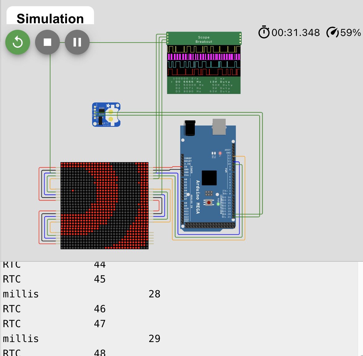
Here's a demo, but you have to run it on a slow machine to see the point:
![]() RTC outpaces simulated passage of time.
RTC outpaces simulated passage of time.
The loop() just calls a project loop() that demands huge resources and slows simulation down on my tablet, as well as the loop I post here which uses two means of marking the passage of time:
void loop()
{
  loopRTC();
  loopBOG();  // bog this down! and entertain us whilst
}

// advance and print a counter based on millis
// advance and print a counter based on the RTC

int millisCounter;
int rtcCounter;

void loopRTC()
{
  static unsigned long lastTime;
  unsigned long ms_now = millis();

  if (ms_now - lastTime >= 1000) {
    lastTime = ms_now;
    Serial.print("millis                  ");
    Serial.println(millisCounter);
        millisCounter++;
  }

  DateTime now = rtc.now();

  static byte lastSecond;
  byte thisSecond = now.second();
  if (lastSecond != thisSecond) {
    lastSecond = thisSecond;
    Serial.print("RTC            ");
    Serial.println(rtcCounter);
        rtcCounter++;
  }
}
I think any use of time, RTC or PIR timeout or whatever, should be based on the simulated clock. If the sim slows down, so must all things attached, or some sketch logic would not be faithfully (however "really" slow) execute.
a7
I'll see how it runs when I have the Arduino itself. My PC is a rotting potato.
I'm happy to have a decently working code for now. Although I'll probably have to change the sunset, I'll see how the LEDs behave in real life but I think ChatGPT made the mistake of starting each color transition on high brightness for that color. I'll also check out some of the other sketches that ChatGPT wrote, it takes several different approaches.
The resource I used for the clock said DS3231 on it, but the graphic for it in the simulator says DS1307. Best to work on fixing it when I have the actual hardware I think. Changing RTC_DS3231 to RTC_DS1307 in the sketch didn't seem to change much though.
Any mistakes? I didn't write the voltages on it, but it's 5V all through the circuit, right?
Interesting. I'm seeing 3 RTC prints per millis print on my pc.
I think the demo would better avoid millis(), as that can go wrong with smart LED show() calls.
But the problem is real. My larger first proof just had the RTC printing the time, which time races ahead of the simulated running time. Shouldn't.
I'd say you need a new PC… both versions of my experiments run at 100 percent real time on the desktop machines that get any regular use, and those are pandemic years old at this point.
Any excuse, amIRight? ![]()
Good to know. For many, just as entertaining.
For simple use cases, there is no difference between the parts, and they can be swapped one for the other, library or module.
Well maybe not the library. I use wire(), not any of the several thousand RTC libraries all named the same, or nearly the same.
For mere time and date feed the cat now stuff direct addressing is fairly easy, and not a bad learning project. Even if you always use libraries, it is good to know what you might have to do should you find yourself dealing with a chip that hasn't attracted the same level of support.
a7
Mine is more like Spanish flu pandemic old.
Yeah, I've been needing one for a while.
I noticed that the ChatGPT code includes both RTClib.h and Wire.h. Do you think that could cause conflicts?
Don't know, just a guess. I made this thread a few days ago. I've had to learn about circuitry too, I didn't even really know what an Arduino is at first. The ChatGPT code just gives me a place to start. I think it works decently already. I'll see how it does in real life. I've learned quite a bit from just studying the code ChatGPT wrote and trying to understand what it's doing. I'd say I understand about half of it by now.
I was thinking of getting the 60 LEDs per meter one with IP65. 60 leds might be overkill but better to have too many LEDs than too few, I don't want to get hotspots.
I want to start ordering things. I found a 1000uF 35V capacitor. I found a Neopixel 60 LED IP65 strip. I found jumper cables. I found a DS3231 RTC module. I found a DC power adapter with screws. I have 3 more decisions to make and then I'm ready to order.
1: I found an Arduino Rev3 clone (a clone is 7.5 euros with cable and an original is 27 euros with cable). Is it worth spending the extra money?
2: I found 470 Ohm resistors. One says 1/2W 5%, and the other says 1/4W 5%. Which should I get?
Then something about the power supply. I was looking for 5V 6A power supplies but they're hard to find. Turns out I misremembered this post, and thought I needed 6A. What I should have remembered from this post is that if I see one with 6A, it is sure to be enough.
Adafruit website says this:
And this:
To estimate power supply needs, multiply the number of pixels by 20, then divide the result by 1,000 for the “rule of thumb” power supply rating in Amps. Or use 60 (instead of 20) if you want to guarantee an absolute margin of safety for all situations. For example:
60 NeoPixels × 20 mA ÷ 1,000 = 1.2 Amps minimum
60 NeoPixels × 60 mA ÷ 1,000 = 3.6 Amps minimum
Since I'm a novice I think I should follow the 3.6A minimum. A 5V 4A power supply is much easier to find. In the end I will actually have an 80 cm strip, which is 48 NeoPixels, which comes out to 2.9A. But I might want to play with it before cutting it, and I don't want to accidentally fry anything.
Then there's this post:
3: Am I still in 18AWG territory if I go for a 4A power supply, or should jumper cables be able to handle it? They come in packs of 40, so I'm thinking I can just cut the connectors off some of them and use just the wire if necessary.
Draw all these in a circuit diagram, with numbers.
I drew this earlier:
So the 6A on the power supply should be 4A. What other numbers should I add?
If you use an external 5vdc power supply, connect it to a 5v pin. If the power supply is 7.5vdc to (max V... some say 12, some say 20), connect it to Vin.
Got it, thanks. Can I just make a Y split in the wire that goes from the 5V on the Arduino to the VCC on RTC module, and connect it to a Y split in the wire between the power supply and the 5V on the LED strip?
Do you have a drawing?