Hi
I am using the elm - chan's FFT library to build a 7 band LED based spectrum analyser.Currently I am using FFT_N = 64 and 9.6ksps settings.
As per my understanding goes,The fundamental frequency will be 150Hz and that will be reflected in the output Buffer[1] value and so on.(Buffer[0] is the DC compnent,right??)
I am also getting responses in the desired array locations(Suppose when applying 900Hz,I am getting max values in the buffer[6] position).
The buffer[0] is always giving a value around 32k and Buffer[1] around 13k.My question is
1)Why buffer[1] is giving such a high value??Isn't it reflecting the 150Hz frequency??
2)What is the Max values for the buffer outputs??For say what will be the Max value for Buffer[6] when applying a 900Hz signal??
3)Is the ouput values reflecting the Vrms value of the particular frequency band??How to scale it in a 1-10 range as I have 10 LED array for each band??
Please answer somebody....
The best approach is to write a program that prepares a buffer with signal values to be transformed, then present this buffer to the FFT routine to be transformed, and examine the output.
That way you know exactly what result to expect.
Start with a constant DC value. That should return the DC value in output buffer location[0] and zeros everywhere else.
Then write a program that generates a single sine wave of known frequency. That should return a peak in the correct element of the output buffer and zeros everywhere else.
-
It really depends on what signal you are applying. The frequency steps are fs/N.
-
It is proportional to the input level, and depends on whether your library scales or not.
-
You need to play with it to scale it
Now let me give you some real data that I noticed....
When I am applying a 900Hz signal at my laptop output and running a FFT on my Rigol 1102(sample rate 250ksps),then I am getting a 1v Vrms value.
But
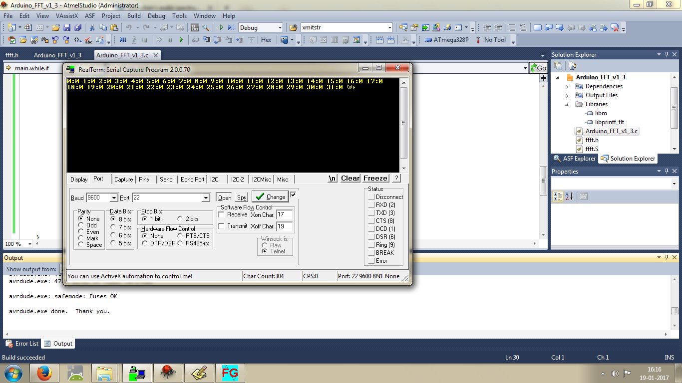
When i am running this library and applying the same 900Hz to the circuit and then reading the 6th buffer element(Buffer[6]) on realterm,Then it is showing a value of around 4.4k.
My question is what i am supposed to understand or how to process the output of the buffer???I am attaching a screenshot for your ref.....
One thing is for sure,that i am getting values at the desired buffer elements(Excepting 0 & 1) for any known frequency....
For say,location 6 for 900Hz signal....Please check the Pic attached....

Remove the DC offset by subtracting from each element the average value of the input array, and see what happens.
Please be a little bit elaborate....
The original example program is substracting 32768 from The ADC output and then storing the data to the buffer....like this below
*buffer++ = ADC - 32768;
I also tried with that.But that is only changing the Buffer[0] and Buffer[1] data.Rest are being the same!!
The arduino does not measure volts, it measures counts from 0 to 1023. You need to scale things.
That I know!!But my main concern is what will be the typical output value range??For say should it be between 0 to 1023??That what I am asking....
Ok guys!!I have found a problem in the original program.The main capture program was written like this below
void capture_wave (int16_t *buffer, uint16_t count)
{
ADMUX = _BV(REFS0)|_BV(ADLAR); // channel
do {
ADCSRA = _BV(ADEN)|_BV(ADSC)|_BV(ADATE)|_BV(ADIF)|_BV(ADPS2)|_BV(ADPS1)|_BV(ADPS0);
while(bit_is_clear(ADCSRA, ADIF));
*buffer++ = ADC - 32768;
} while(--count);
ADCSRA = 0;
}
ADLAR bit was set so the data must be left adjusted.So in order to read the ADC value,one must read the ADCH register only to get a 8 bit data.But the author is reading the whole ADC register after ADLAR bit is set.
Now I rewrite the program using ADC interrupt like this below....
volatile uint8_t position = 0;
extern volatile uint8_t uart_data;
int16_t capture[FFT_N]; /* Wave captureing buffer /
complex_t bfly_buff[FFT_N]; / FFT buffer /
uint16_t spektrum[FFT_N/2]; / Spectrum output buffer */
void adc_init(void)
{
ADMUX |=(1<<REFS0);//Internally connected to Vcc with external cap on the pin
ADCSRA = _BV(ADSC) | _BV(ADEN) | _BV(ADATE) | _BV(ADIE) | _BV(ADPS2) | _BV(ADPS1) | _BV(ADPS0);
}
ISR(ADC_vect)
{
if (position >= FFT_N)
return;
capture[position] = ADC;
position++;
}
int main(void)
{
char buf1[10];
uint16_t temp;
uart_init();
adc_init();
sei();
while(1)
{
if(uart_data == 's')
{
fft_input(capture, bfly_buff);
fft_execute(bfly_buff);
fft_output(bfly_buff, spektrum);
for (uint8_t i=0;i<FFT_N/2;i++)
{
temp = spektrum*;*
- sprintf(buf1,"%u",i);*
- uart_sendstring(buf1);*
- uart_send(':');*
- sprintf(buf1,"%u",temp);*
- uart_sendstring(buf1);*
- uart_send(' ');*
- }*
- uart_sendstring("\r\n");*
- position = 0;*
- uart_data = 0;*
- }*
- }*
}
Now I am attaching two screenshots applying 900Hz signal to the ADC and in the other nothing is applied and at last,I am getting 0s.
But still now i am confused about the output value range.....Please reply!!