EMG amplifier/AD8402 controlling problem

Hello! First time posting here. I am a beginner when it comes to electronics and I have to work on a project that requires a lot of Arduino knowledge. I want to create an EMG amplifier using this schematic (the first one is the original one - Figure 8 Nerve Impulse Amplifier and the second one is the one that I am using, instead of the Rg I added the digital potentiometer AD8402 because it is a must to have an automation part - I have to control the digipot through Arduino, while the rest of the circuit is powered by 2 +9V batteries).

My teacher told me to put a 1k braking/brake resistor in series with the 2 Rgs from the LT1167 (I wish I knew why lol), like this
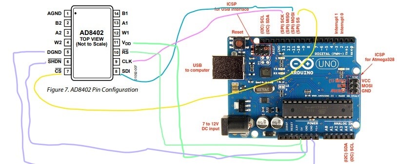
My problem is that I have no idea what code should I use to control the AD8402 digipot, which pins (both from AD8402 and Arduino) should I use for the code. I found these 2 codes but apparently they are for AD8403.

  1. /*
    Digital Pot Control

This example controls an Analog Devices AD8403 digital potentiometer.
The AD8403 has 4 potentiometer channels. Each channel's pins are labeled
A - connect this to voltage
W - this is the pot's wiper, which changes when you set it
B - connect this to ground.

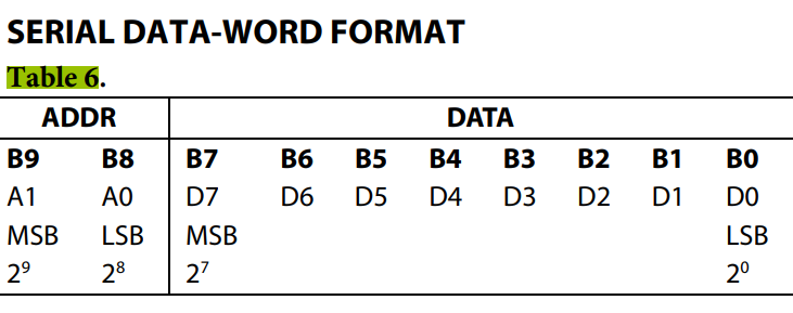
The AD8403 is SPI-compatible. To command it you send two bytes.
The first byte is the channel number starting at zero: (0 - 3)
The second byte is the resistance value for the channel: (0 - 255).

The AD8403 also contains shutdown (SHDN) and reset (RS) pins. The shutdown
pin disables all four of the potentiometers when taken low and enables all
pots when high. The values of the pots can be adjusted while shutdown is active.
The reset pin sets all of the pots back to their center value when taken low.
Reset may or may not be useful for your particular application. In this circuit
reset is simply tied to +5v to keep it inactive.

The circuit:

  • All A pins of AD8403 connected to +5V
  • All B pins of AD8403 connected to ground
  • An LED and a 220-ohm resisor in series connected from each W pin to ground
  • RS - to +5v
  • SHDN - to digital pin 7 and a pull down resistor
  • CS - to digital pin 10 (SS pin)
  • SDI - to digital pin 11 (MOSI pin)
  • CLK - to digital pin 13 (SCK pin)

Thanks to Tom Igoe and Heather Dewey-Hagborg for their code which this was built on.

*/

// inslude the SPI library:
#include <SPI.h>

// set pin 10 as the slave select for the digital pot:
const int slaveSelectPin = 10;
const int shutDownPin = 7;

void setup() {
// set the slaveSelectPin as an output
pinMode (slaveSelectPin, OUTPUT);
// set the shutDownPin as an output
pinMode (shutDownPin, OUTPUT);
// initialize SPI
SPI.begin();
//Shutdown the pots to start with
digitalWrite(shutDownPin, LOW);
//Set all pots to zero as a starting point
for (int channel = 0; channel < 4; channel++) {
digitalPotWrite(channel, 0);
}
}

void loop() {
digitalWrite(shutDownPin, LOW);
int channel = 0;
// Loop through the four channels of the digital pot.
for (int channel = 0; channel < 4; channel++) {
// Change the resistance on this channel from min to max.
// Starting at 50 because the LED doesn't visibly change
// before that point.
digitalWrite(shutDownPin, HIGH);
for (int level = 50; level < 255; level++) {
digitalPotWrite(channel, level);
delay(2);
}
// wait a bit at the top
delay(5);
digitalWrite(shutDownPin, LOW);
// change the resistance on this channel from max to min:
digitalWrite(shutDownPin, HIGH);
for (int level = 0; level < 205; level++) {
digitalPotWrite(channel, 255 - level);
delay(2);
}

}
digitalWrite(shutDownPin, LOW);

}

void digitalPotWrite(int address, int value) {
// take the SS pin low to select the chip:
digitalWrite(slaveSelectPin, LOW);
// send in the address and value via SPI:
SPI.transfer(address);
SPI.transfer(value);
// take the SS pin high to de-select the chip:
digitalWrite(slaveSelectPin, HIGH);
}

  1. #include <SPI.h>

const int slaveSelectPin = 10;
int value=0;

void setup(){
Serial.begin(115200);
pinMode(slaveSelectPin, OUTPUT);
SPI.begin();
digitalPotWrite(0,0); // remember to initialize
digitalPotWrite(1,0); // remember to initialize
}

void loop(){
Serial.print("Hello\n");

for (byte channel = 0; channel < 2; channel++){
for (byte level = 0; level < 255; level++){
digitalPotWrite(channel, level);
delay(2);
Serial.print(0+channel);
Serial.print(" ");
Serial.println(0+level);
}
}

}

void digitalPotWrite(byte address, byte value){
digitalWrite(slaveSelectPin, LOW);
SPI.transfer(address);
SPI.transfer(value);
digitalWrite(slaveSelectPin, HIGH);

I don't know which addresses, channels and pins to use in my case. My teacher also told me to not have a GND so that I will have symmetrical power supply (?) and to only power the LT1167/circuit by the 2 +9V batteries. I will then connect the circuit to some surface electrodes for the EMG signaIs, I will have to use Visual Analyser both as a signal generator and as a digital measuring device. I am really confused and don't know what to do. Sorry for my not so best English and weird words, I am really a complete beginner. I would love to get some help :frowning: Thank you!

Welcome to the community.

It will help others help you if you put your/the code in code tags see </> on the editor ribbon. You should also read the forum's rules and suggestions for getting the best help.

Before we start could I ask what class this is for and what is your major? I ask because it helps to know your current level of understanding.

John

This is for the Biomedical Engineering class and my major is Automation Engineering. Thank you for your kindness!

  1. the added resistor across the Rg's changes the gain. The gain = G = (49.4kΩ/RG) + 1
    so the smaller Rg is the greater the gain.

  2. So it looks like the digipot is supposed to allow the Arduino to control the gain.
    look at this forum post for code to control your digipot Forum AD8402 post

I understood the Rg part. I talked to my teacher today and he told me to use this code : Example code for controlling an AD8403 Digital Potentiometer. Please see https://github.com/matt448/arduino for the latest version of this code. · GitHub
And instead of int channel = 0; channel < 4; channel++ I should write this int channel = 0; channel < 1; channel++ (because there are only 2 channels when it comes to AD8402). Also, instead of int level = 50; level < 255; level++, int level = 0; level < 255; level++ (because we decided that the Rgain should be 10k max).
But I have no idea how to customize the code for AD8402. I don't know which pins should I use from AD8402 to Arduino (the teacher told me to use only the SPI pins) and also I don't know how can I write the address and value in these sections : digitalWrite(slaveSelectPin, LOW); // send in the address and value via SPI: SPI.transfer(address); SPI.transfer(value);
I read that I should do it according to this table, found in the AD8402 datasheet :


So the address can be either 00 or 01 because AD8402 has 2 channels and the value can be from 0 to 255, value written as 8 bits?

I've not used this part however the AD8402 and AD8404 are identical except for the two additional outputs.

So, Set up your AD8402 with the arduino but don't connect your EMG amp. Use an ohmmeter to measure the outputs.
Use the linked code but add some serial.prints to places where there are writes.

Also look at the line " for (int channel = 0; channel < 4; channel++) "
and imagine what you might change to go from a 4 channel to a 2 channel device.

Is this how I should set up the digipot?

My teacher told me to not use the GND like it is indicated here : Example code for controlling an AD8403 Digital Potentiometer. Please see https://github.com/matt448/arduino for the latest version of this code. · GitHub

The circuit:

  • All A pins of AD8403 connected to +5V
  • All B pins of AD8403 connected to ground
  • An LED and a 220-ohm resisor in series connected from each W pin to ground
  • RS - to +5v
  • SHDN - to digital pin 7 and a pull down resistor
  • CS - to digital pin 10 (SS pin)
  • SDI - to digital pin 11 (MOSI pin)
  • CLK - to digital pin 13 (SCK pin)

Also he told me to use a resistor but I don't know where should I put it, why and what value... I have some 1k and 10k resistors at home. Thank you so much for helping me! I am trying my best to learn and understand, sadly we did not learn these things at university yet we have to do projects like this.

You MUST connect the AS8402 DGND (digital ground) to the Arduino ground

You MUST connect Vdd to Arduino 5V.

You MUST ground SHDN\

You should read page 22 of the device documentation. It describes the various input configurations.

Hello again. I am pretty much desperate because I have 4 days left and the circuit is not done and nothing seems to work. I have tried to test out the digipot, connecting the pins like this


and using this code
`#include <SPI.h>

const int slaveSelectPin = 10;

void setup(){
Serial.begin(115200);
pinMode(slaveSelectPin, OUTPUT);
}

void loop(){
for (byte channel = 0; channel < 2; channel++){
for (byte level = 0; level < 255; level++){
digitalPotWrite(channel, level);
delay(10);
Serial.print(0+channel);
Serial.print(" ");
Serial.println(0+level);
}
for (byte level = 0; level < 255; level++){
digitalPotWrite(channel, 255 - level);
delay(10);
Serial.print(0+channel);
Serial.print(" ");
Serial.println(255-level);
}
delay(500);
}
}

void digitalPotWrite(byte address, byte value){
digitalWrite(slaveSelectPin, LOW);
SPI.transfer(00);
SPI.transfer(00000001);
digitalWrite(slaveSelectPin, HIGH);
}`
and when I go to the serial monitor nothing happens. I also tried using an ohmmeter but nothing changes after I use the code for the digipot. I am getting this error "In function digitalPotWrite(byte, byte), warning: large integer implicitly truncated to unsigned type [-Woverflow]". Sorry for my insistence but I am really desperate and I have no one that knows this type of things. Thank you again for your help despite me having 0 knowledge and asking too many questions.

I'm not so good with code. However I to get down to basics I would (as a test) remove all your for loops and simply set the digipot to some middle value.

One channel, No loops, just one time through. See if you can set a value you can read with your ohm meter.
BTW the above "... one channel ... etc" is where you should always start.

HAve you tested to see if your spi interface is working? I had some problems

Your diagram is showing an arduino uno - can you confirm that is what you are using?

Hi! I found the problem. I connected the SHDN pin (which is active LOW) to the Arduino GND pin. The rest of the connection is like this :


And now the code works :slight_smile:

This topic was automatically closed 120 days after the last reply. New replies are no longer allowed.