Encoder reading with interrupts

/* Encoder Library - TwoKnobs Example
 * http://www.pjrc.com/teensy/td_libs_Encoder.html
 *
 * This example code is in the public domain.
 */

#include <Encoder.h>

// Change these pin numbers to the pins connected to your encoder.
//   Best Performance: both pins have interrupt capability
//   Good Performance: only the first pin has interrupt capability
//   Low Performance:  neither pin has interrupt capability
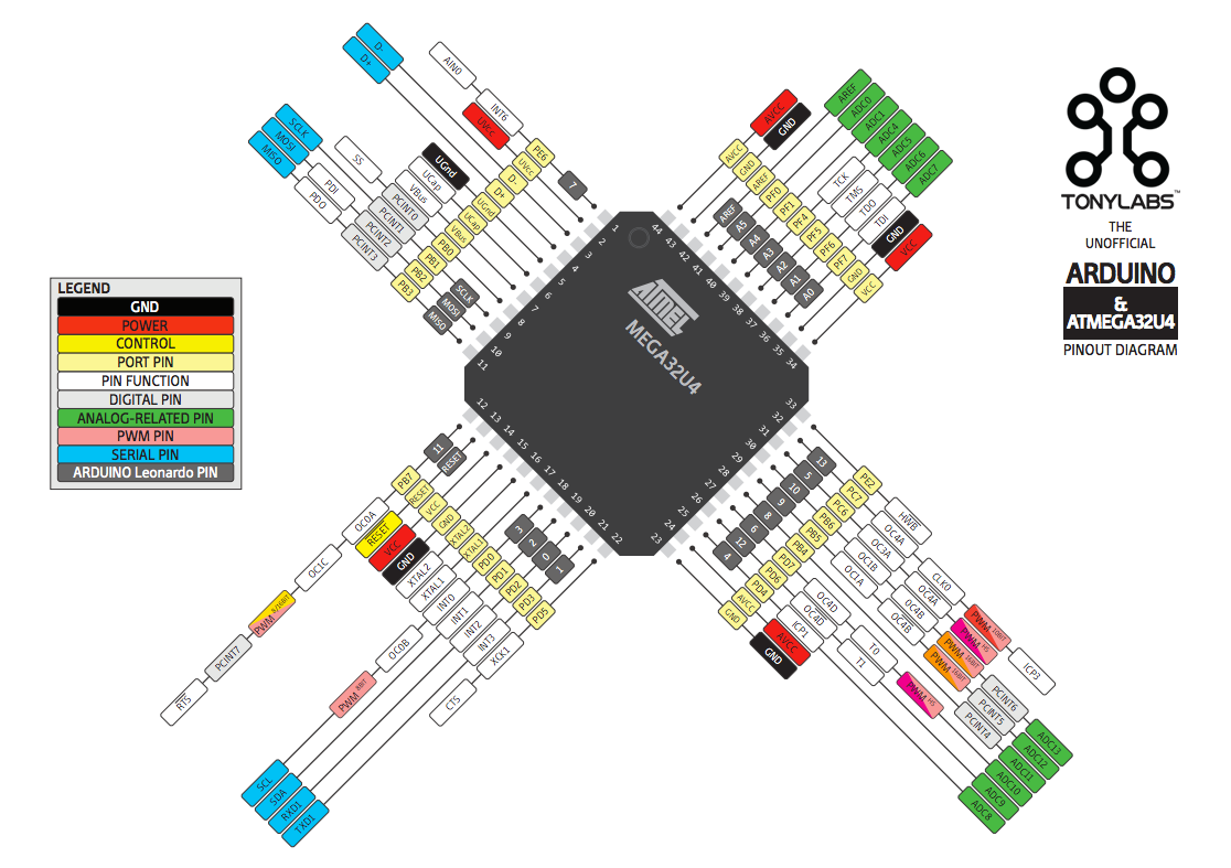
Encoder knobLeft(SS, 8);
Encoder knobRight(MISO, 13);
//   avoid using pins with LEDs attached

void setup() {
  Serial.begin(9600);
  Serial.println("TwoKnobs Encoder Test:");
}

long positionLeft  = -999;
long positionRight = -999;

void loop() {
  long newLeft, newRight;
  newLeft = knobLeft.read();
  newRight = knobRight.read();
  if (newLeft != positionLeft && newLeft % 4 ==0 || newRight != positionRight && newRight % 4 ==0 ) {
    Serial.print("Left = ");
    Serial.print(newLeft/4);
    Serial.print(", Right = ");
    Serial.print(newRight/4);
    Serial.println();
    positionLeft = newLeft;
    positionRight = newRight;
  }
  // if a character is sent from the serial monitor,
  // reset both back to zero.
  if (Serial.available()) {
    Serial.read();
    Serial.println("Reset both knobs to zero");
    knobLeft.write(0);
    knobRight.write(0);
  }
}

After adding:
% 4 ==0
and val/4

I have counting by 1. But it doesnt works properly for left knob. SS and 8 - they are PCINT. For right knob work ... good but not ideal for all steps - MISO and 13 pin, only MISO is PCINT.

Problem with left knob:

  • start from 0 position/count, turn right of leftKnob- I got nothing. Then turn right of rightKnob - i got -1 (this move for check if leftKnob has still 0 count):

11:08:36.687 -> Reset both knobs to zero

11:08:36.687 -> Left = 0, Right = 0

11:08:53.421 -> Left = 0, Right = -1

11:08:53.888 -> Left = 0, Right = 0

then turn left leftKnob:
then I got new print in serial monitor of "0" for leftKnob:
11:09:48.631 -> Left = 0, Right = 0

again turn left:
11:10:28.146 -> Left = 1, Right = 0 , its ok

then turn right, should go to 0, but it stuck at 1, nothing change in serial monitor, but after turning rightKnob ... I got "0" for leftknob and -1 for rightknob

11:11:04.374 -> Left = 0, Right = -1

maybe problem is with leftKnob because it uses both pins as PCINT? Maybe it would be good to turn off PCINT for second pin of leftKnob?

1 Like

The PJRC Encoder library does not use PCINT, it only enables interrupts for pins that support attachInterrupt. For the Arduino Micro, these are pins 0, 1, 2, 3, 7.

from Paul Stoffregen sucks !
This library is not using the state-table-method

I did some research on how to setup a timer interrupt on Atemag 32U4
and found this library

this not a ready to use solution but a base to build upon.

The code has a functions timer-handler
oinside these functions you call
these lines from the rotary-object

  unsigned char result = rotary.process();

  // depending on having detected rotation
  if (result == DIR_CW) {
    myCounter++;
  }
  else if (result == DIR_CCW) {
    myCounter--;
  }

best regards Stefan

Atemag 32U4 has enough interrupt-enabled pins to support 2 Encoders. So, I wouldn't bother with timer interrupts.

Pin Change interrupts are on all pins! :slight_smile:
(Ooops... Only 8 pins on ATmega32U4!)
You only have to check which one of the two triggered the interrupt.

Point being?

Of course - not.


Also you can see in datasheet of 32u4. https://ww1.microchip.com/downloads/en/devicedoc/atmel-7766-8-bit-avr-atmega16u4-32u4_datasheet.pdf

Sorry. Only ATmega328p has PCINTs on all pins:
https://www.researchgate.net/figure/Atmel-MCU-ATmega328-and-the-Arduino-pin-out_fig10_312372376
32U4 has only PC0...7, then 8 pins.

Here is an example on ATmega328p:

In the ISR I verify if the encoder switch have been pressed or encoder state, converted from Gray to decimal, has changed from 1 to 2 (CW) or from 3 to 2 (CCW).

32u4 has five interrupt-capable pins. Go back and read Post #7. Open the MultipleEncoder example. Modify it for only two encoders and use four of the interrupt-capable pins.

I have taken the TimerInterrupt.h-library from here

and combined it with the rotary-library from here

I modified this example-code from the TimerInterrupt.h-library

I adjusted the arduino-IDE to Arduino micro and this code does compile

/* Demo-Code that uses the Rotary-library from GitHub-User https://github.com/buxtronix
 * using his library https://github.com/buxtronix/arduino/tree/master/libraries/Rotary  
 * in combination with a timer-interrupt executed 10000 times per second
 * Copyright 2023 StefanL38. Licenced under the GNU GPL Version 3.
 * A T T E N T I O N ! 
 * this demo-code uses Timer1 which is used by other libraries too. 
 * This means using this code can interfere with other libraries
 * causing malfunction of both
 * 
 * This demo-code uses the TimerInterrupt.h-library from here
 * https://github.com/khoih-prog/TimerInterrupt/tree/master
 * 
 * The examples in the GiPo show how to use different timers
 * The demo-code simply prints the value of variable myCounter 
 * each time the value of the variable changes
 */

#define USE_TIMER_1     true

#if ( defined(__AVR_ATmega644__) || defined(__AVR_ATmega644A__) || defined(__AVR_ATmega644P__) || defined(__AVR_ATmega644PA__)  || \
        defined(ARDUINO_AVR_UNO) || defined(ARDUINO_AVR_NANO) || defined(ARDUINO_AVR_MINI) ||    defined(ARDUINO_AVR_ETHERNET) || \
        defined(ARDUINO_AVR_FIO) || defined(ARDUINO_AVR_BT)   || defined(ARDUINO_AVR_LILYPAD) || defined(ARDUINO_AVR_PRO)      || \
        defined(ARDUINO_AVR_NG) || defined(ARDUINO_AVR_UNO_WIFI_DEV_ED) || defined(ARDUINO_AVR_DUEMILANOVE) || defined(ARDUINO_AVR_FEATHER328P) || \
        defined(ARDUINO_AVR_METRO) || defined(ARDUINO_AVR_PROTRINKET5) || defined(ARDUINO_AVR_PROTRINKET3) || defined(ARDUINO_AVR_PROTRINKET5FTDI) || \
        defined(ARDUINO_AVR_PROTRINKET3FTDI) )
#endif

// To be included only in main(), .ino with setup() to avoid `Multiple Definitions` Linker Error
#include "TimerInterrupt.h"

#define TIMER1_INTERVAL_MS    1
 
#include <Rotary.h>

// Rotary encoder is wired with the common to ground and the two
// outputs to pins 5 and 6.
const byte channel_A_Pin = 5;
const byte channel_B_Pin = 6;
Rotary rotary = Rotary(channel_A_Pin, channel_B_Pin);

unsigned long myISR_TimerFrequency = 10000;
// myCounter that will be incremented or decremented by rotation.
// as this variable is changed in an interrupt-service-routine
// this variable MUST !! be declared volatile to make sure 
// that it works properly !
volatile int8_t myCounter = 0;
int8_t last_myCounter = 0;


void TimerHandler1() {
  unsigned char result = rotary.process();

  // depending on having detected rotation
  if (result == DIR_CW) {
    myCounter++;
  }
  else if (result == DIR_CCW) {
    myCounter--;
  }
}


void PrintFileNameDateTime() {
  Serial.println( F("Code running comes from file ") );
  Serial.println( F(__FILE__) );
  Serial.print( F("  compiled ") );
  Serial.print( F(__DATE__) );
  Serial.print( F(" ") );
  Serial.println( F(__TIME__) );
}


// easy to use helper-function for non-blocking timing
boolean TimePeriodIsOver (unsigned long &startOfPeriod, unsigned long TimePeriod) {
  unsigned long currentMillis  = millis();
  if ( currentMillis - startOfPeriod >= TimePeriod ) {
    // more time than TimePeriod has elapsed since last time if-condition was true
    startOfPeriod = currentMillis; // a new period starts right here so set new starttime
    return true;
  }
  else return false;            // actual TimePeriod is NOT yet over
}

unsigned long MyTestTimer = 0;  // Timer-variables MUST be of type unsigned long
const byte    OnBoard_LED = 13;


void BlinkHeartBeatLED(int IO_Pin, int BlinkPeriod) {
  static unsigned long MyBlinkTimer;
  pinMode(IO_Pin, OUTPUT);

  if ( TimePeriodIsOver(MyBlinkTimer, BlinkPeriod) ) {
    digitalWrite(IO_Pin, !digitalRead(IO_Pin) );
  }
}


void setup() {
  Serial.begin(115200);
  Serial.println("Setup-Start");
  PrintFileNameDateTime();

  Serial.print(F("\nStarting Argument_None on "));
  Serial.println(BOARD_TYPE);
  Serial.println(TIMER_INTERRUPT_VERSION);
  Serial.print(F("CPU Frequency = ")); 
  Serial.print(F_CPU / 1000000); 
  Serial.println(F(" MHz"));

  // Timer0 is used for micros(), millis(), delay(), etc and can't be used
  // Select Timer 1-2 for UNO, 1-5 for MEGA, 1,3,4 for 16u4/32u4
  // Timer 2 is 8-bit timer, only for higher frequency
  // Timer 4 of 16u4 and 32u4 is 8/10-bit timer, only for higher frequency

  ITimer1.init();

  // Using ATmega328 used in UNO => 16MHz CPU clock ,
  // For 16-bit timer 1, 3, 4 and 5, set frequency from 0.2385 to some KHz
  // For 8-bit timer 2 (prescaler up to 1024, set frequency from 61.5Hz to some KHz

  if (ITimer1.attachInterruptInterval(TIMER1_INTERVAL_MS, TimerHandler1)) {
    Serial.print(F("Starting  ITimer1 OK, millis() = ")); Serial.println(millis());
  }
  else {
    Serial.println(F("Can't set ITimer1. Select another freq. or timer"));
  }
}


void loop() {

  BlinkHeartBeatLED(OnBoard_LED, 250);

  // check if value has changed
  if (last_myCounter != myCounter) {
    // only if value REALLY HAS changed
    byte difference = abs(last_myCounter - myCounter);
    if (difference != 1) {
      Serial.println("difference != 1 counter jumped !!");
    }
    last_myCounter = myCounter; // update last_myCounter
    Serial.print("myCounter=");
    Serial.println(myCounter);
  }
}

if you want to use two encoders you will have to define a second rotary-object

best regards Stefan

Again, my question ... why bother with timer interrupts?

Another option that could be used.

As an arduino micro = Atmega 32U4 has 5 interrupt-pins the new-enocder-library works very well.

I have modded my connection to get on all pins of both encoders PCINT.

I have opened your MultipleEncoders example, but I dont see where I should put pinout, max, min value and othere parameters.

#define FULL_PULSE 0
or
#define HALF_PULSE 1

I should write before #include "NewEncoder.h" or after? Or I dont need to write this defines only write full/half in this formula:

"NewEncoder(uint8_t aPin, uint8_t bPin, int16_t minValue, int16_t maxValue, int16_t initalValue, uint8_t type = FULL_PULSE);" ?

First, the NewEncder library does not support "Pin Change Interrupts (PCINT)". It only supports "External Interrupts". These are the interrupts that work with the attachInterrupt() function. I've indicated them in the diagram:

Where do you see those defines? They are only in the library source code that you don't need to open. The only thing you need to open is MultipleEncoders.ino!

Once you open that, the only thing you need to change is the instantiation of the NewEncoder objects:

NewEncoder encoders[] = {
  { 0, 1, -20, 20, 0, HALF_PULSE },
  { 20, 21, 0, 50, 25, FULL_PULSE },
  { 5, 6, -25, 0, -13, HALF_PULSE },
  { 11, 12, -10, 25, 8, FULL_PULSE }
};

In your case there would only be two NewEncoder objects in the array. The arguments to the NewEncoder class's constructor are thoroughly documented in the README:

Ok, so Im still loking for library with PCINT.

SCL SDA I need for i2c.
TX RX UART I need for communication between devices.

Look up pinchangeinterrupt in the IDE (2.0.2) library folder.

If you use the NewEnocer-library you specifiy 4 IO-pins out of these 5

and you are done.

The encoder-counter wil be updated by interrupt autmatically

best regards Stefan

NewEncoder-library uses INT, not PCINT. INT pins I need for i2c and uart.

PJRC also use INT, not PCINT.

Regards
Mateusz

I have tested my code on an arduino-Uno with a rather low timer-frequency of checking the IO-pins "only" 1000 times per second. For slow turning the encoder-shaft this surely works 100% reliably

for fast rotating the encoder-shaft - I mean as fast as I can by hand - using thumb and point-finger directly rotating a 6 mm shaft with finger-snipping to make it as fast as possible but pretty uncontrolled regarding how far the rotation will be
it works 100% reliably

If you use a knob with a diameter bigger than 6 mm the rotational speed will be lower.
(imagine you want to rotate a 40cm-knob 10 full rotations per second. Not possible by hand)

The from me shown code is able to catch ALL encoder-pulses
regardless of what your code is doing.
Except if your code is inside another interrupt and stays inside this interrupt-code for a longer time than the encoder-pulse is lasting.

This problem is still there if you use PCINT.
If I remember right your encoders control volume and input-selector
If a single encoder-pulse would be ever missed the consequence would only be that you have to turn the encoder for another tick to change the volume that one more tick or to change input-channel one more time.

This means with the timer-interrupt you can use whatever IO-pin you like and no longer have to care about using a particular IO-pin which has some additional functionality like beeing able to have PCINT or whatever

best regards Stefan