Yes, I was afraid of that. I tought the current didn't matter.
Just plugged a 1000 W heater and in the out.png screenshot you can see the output with never adjusting the phase shift which by default is 1.7.
In the out 2.png you can see the output with the phase shift adjusted to -1 and things have improved, for now.
Using an op-amp made things worse. I have worked with an op-amp before and I know how to use it.


Your results look not too bad ! (on a resistive load...). Your connections are correct, this is the most important part of the job ! Mistakes are easily done, and can destroy the Arduino's ADC (I destroyed a Pro Mini ADC while I was trying to filter the crappy signal from a crappy miniature transformer like the one you're using).
What op amp did you use ? Some need compensation or they will oscillate. I use CA3130 (single rail power supply as low as 5V), and they do need compensation.
On a reactive load, I am skeptical because of your voltage transformer...
A 1000W heater is NOT a reference load !!! They are often winded resistors (nearly neglictable for 50Hz...), their power ratings are rather inacurate and vary with temperature. Did you measure mains (need a suitable true RMS DMM), did you measure mains current (need a suitable true RMS DMM), did you measure hot heater resistance ? (let it heat up, then disconnect and measure ohms)
I have been using a 2000W heater, but measured (the hard way, not software) 1850W.
Measure with caution : suitable class IV DMMs, oscope isolated probes (few people have, as it costs a lot), isolation transformer for the DUT (easy to make).
You also can calibratre the probes (transformers), and then do some calculation using true measured values for your components. Amps transducer can be safely tested and measured using a big low voltage transformer, for example 250VA 15V, as it will easily output 10 amps on a suitable resistor (I use big rheostats).
You can make your own isolation transformer for voltage transducer calibration : just use two identical (or not...) transformers : primary -> secondary -> secondary -> primary ; this way, you get 230V completely isolated from mains, with no connection between neutral and earth, and less risks for you , your DMM (if it is a earthed bench DMM), and/or your oscope. (don't do that if you don't understand)
Another point : openenergymonitor (AFAIR as I dont use this library) uses a linear interpolation algorithm for phase correction. Not that good. Better results with cubic interpolation (but needs 4 points, not 2).
You will also get better results with a follower op amp between the 1:2 divider (10k/10k) and the transformers common. Easy, and it is worth it.
I'm not that well equipped. I can't afford an oscope. A close friend of mine lend me his $200 Fluke multimeter which is as precise as you can get.
The op-amp I used is an LM358 which, I guess, explains the "getting worse" part.
I'll get to measuring and come back with new results.
Can I update the code to use cubic interpolation?
PS. Instead of one 470k from each reference I used a 330k in series with an adjustable 100k resistor in order to get 2.5V on the input pins. It shouldn't affect the output.
Your opamp should work ! It is intended for 5V one rail supply ! It could oscillate and need a capacitor. It could also need a load on its output. Difficult to know without an oscope... And I cannot test for you at the moment as I have CA3130 only. I have to order some components, I will get a couple of them (I need single rail low voltage double and quad opamps)...
This being said, your circuit seems to work... You're just facing probes issues that cannot be solved with software.
maybe you could :
- re use the voltage transformer for some low power circuit
- take the current transformer apart, and replace the burden. Or replace it with a CT-1005A (or other depending on the current to be measured)
I got 2x CT-1005A for 3.63 USD off eBay !!! (and killed one  )
)
I found my first oscope in a junkyard : cost = zero ! A used CRT oscope can be found for very little money.
The linear interpolation can not be replaced with a cubic, because Openenergyminitor filters and computes RMS and power on the fly (AFAIR...) : cubic could be implemented, but, as is, it would reduce the sample rate and the accuracy.
It can be used with a different approach for the software, or it will need a faster ADC and controller that the Atmega328.
What makes things somewhat difficult with openenergymonitor is that it continuously samples, filters and computes inputs : complicated algorithms.
On the contrary, I do 300 successive readings every interval (300x V and 300x I, interlaced), so they are 112µs+112µs+112µs... : interpolation is far easier ! It produces 90 points per period (50 or so for openenergymonitor, as it does calculations on the fly). Sampling takes 60 ms or so (3x 50Hz periods) to fill two arrays, and then there is a lot of time for calculations. Much simpler and easier ! But goals are different.
I will post something when it will be finished (PCB still to etch + final testings, pics, BOM, etc.)
Some readings about cubic interpolation : Interpolation methods
The second one seems to give better results (Catmull-Rom interpolating spline).
I am wondering if a Atmega328 could do FFT and rephase signal with FFT data... It is an interesting question... but off topic !
Cubic is absolutely worthless with the probes you use... For the moment, stick with the original design ! It works fine (even if it is overcomplicated if used as a simple watmeter).
With the AX-1500 CT I'm using I have put a 50 Ohm burden resistor so it behaves like the YHDC-013-030 from the Emon guide. As you will see, this CT can output as much as 2 volts with a 200 Ohm burden. In my case I have put 2x 100 Ohm in parallel.
The yhdc 013 030 current sensor has 500mV output at 15A (datasheet).
That's exactly 100 digital steps per 15A. =150mA/step. = 34.5watt/step (on 230v mains).
That is the threshold. Below that, nothing is detected.You can lower that with an opamp to 10watt/step. Opamp gain = 3.5x
If the CT can give what an op-amp outputs, why would I use one? Is the waveform kept between specific values or it won't be susceptible to noise?
@OP
Since you are Arduino Yun based why to use Smart Meter IC/Energy Processor.
http://forum.arduino.cc/index.php?topic=312824.msg2170725#msg2170725
Ton of IC manufactures produce Smart Meter IC include Atmel
http://forum.arduino.cc/index.php?topic=312824.msg2170736#msg2170736
The method of sensor AC:
Voltage Sensing Unit:
- Resistor divider
- AC Voltage stepdown transformer
Current Sensing Unit:
- Current transformer
- Hall effect-based current sensor
- Rogowski coil sensor
- Shunt resistor
Rogowski coil sensor is my favor.
http://forum.arduino.cc/index.php?topic=312824.msg2170749#msg2170749
This would've been perfect but deadline has passed and I'm in a tight spot. What we've accomplished so far should do, with some available and fast adjustments.
I did'nt read correctly the AX-1500 datasheet. It is an external burden. I thought it was internal...
Why do you use a 50 ohm burden ??? (100//100)
you need a 200 ohm burden, not 50 ohm, in order to get 4Vpkpk with 15 amps pkpk at input (roughly 10 amps RMS).
The difference is 2 bit for the ADC.
So this means I won't be needing an op-amp? Won't the higher voltage require some updates to the schematic? The output is maintained at 2.5V.
You don't need anything else than a correctly sized burden. The datasheet allows you to use a 200 ohm burden. (some manufacturers indicate min/max values, but here, you're fine with 200 given the curves). Doing this you will get 4x the resolution.
Someone else already told you this !
Before you connect to the arduino, test with your friend's DMM. It has probably peak to peak and RMS functions. Don't let voltage go over 4 V peak to peak. Or protect analog inputs.
If you are perfectionist, you could calibrate : have a look at the curves, you don't get exactly 2 volts. There's a tiny difference. Is it worth it ? Certainly not !
But one more time, you won't get anything interesting except with resistive loads if you don't replace the voltage sensor ! For example you can not correctly measure power drawn by a transformer + diode bridge + capacitor because of the crappy sine. You could get 20% error or so. Any wall transformer found in a dump will be better.
You're very near to a perfect result !
I have a 9V transformer, like the ones you'll find in a power adapter. Problem is, I think, that's a major source of el.-mg. waves and it might affect the circuitry. This PCB type looks like it won't be a major problem.
It IS an issue, in terms of phase and linearity ! It is easy to see and to measure.
If it was'nt, manufacturers would'nt design and sell specific voltage transformers.
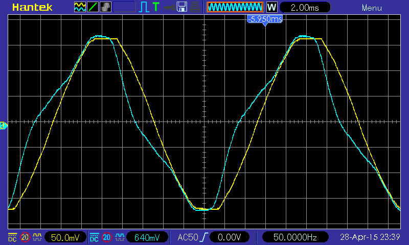
Just for you, I made a a comparison between a miniature transformer like yours (9V 55mA), and a measurement voltage transformer. See attachement.
yellow trace : measurement transformer
blue trace : 9V 55mA
(yes, mains are slightly clipped, it is normal)
(probes are set to 1:10, but not the scope : just x10)
Do you think you can calculate a representative RMS voltage from the blue trace ?
Do you think you can calculate a representative RMS power from the blue trace ?
Do you think Openenergymonitor software will get a correct zero crossing phase reference from the blue trace
Do you think the phase correction factor you used is normal ? (-1 insteed of +1.7 and you can see why on the scope !)
If you can answer "yes" to these questions, then you're fine (or you don't understand how power is calculated and coded) ! On my side, I stopped thinking, I measured and immediatly seen why it did'nt work as expected.
Otherwise, replace this transformer, and you'll turn your circuit into a reliable instrument. Why the hell do you use a measurement current transformer for current, and not a measurement voltage transformer for voltage (or at least a more suitable one, like one of those tested, measured, approved and shown on Openenergymonitor website) ???
The measurement transformer I use is smaller, lighter, and not more expensive than the 9V crap. And it is toroidal.
This is the transformer I'm looking to buy. No waveforms present in the datasheet. This is a different manufacturer and, as suggested, higher power.
Or this one, which has 2x9V output, 600mA:
Before ordering, condider this :
Search on eBay for "TV19 current transformer" or "TV19E current transformer".
Datasheet : http://www.yhdc.com/en/product/521/
$7.50 from eBay. That's what I'm using. Slighly more expensive than the transformers you linked (and that are certainly far better than the tiny one you actually use)
These devices are amazingly small. And most of all, they are measurement transformers. AFAIR, I received it within two weeks from HK. I did'nt find any source in Europe, but it was worth waiting !
Yes !!! Current transformer for voltage !!!
They are current transformers with primary and secondary, 1000:1000 ratio or so.
They have to be used with a resistor in series with the primary ; for testing : 3x 270k 0.25W // = 90k 0.75W (max dissipated power = 0.7 W). For the final version, it will be 39k 1W + 39k 1W in series (=78k, 2 watts).
Burden at secondary : recommanded value, 500 ohm.
The output level is adjusted by varying the primary series resistor. With the given values, it can be connected directly to a 5V Arduino (the same way, with 2.5V middle point). Just now : 3.32V peak to peak for 230V input (0.84V to 4.14V, so there is room for mains peaks)
The yellow trace on the image I posted is taken from a TV19. Tested it against the signal comming from an isolation transformer (for safety !) : phase, visual aspect of the trace and FFT for distorsion. The result was excellent.
Yes it need some power (less than 1 watt), but it is linear, accurate, with very little phase shift and distorsion, and large bandwidth. It is toroidal : no EM disturbance for and from the current sensor. You also can use the TV16 (less primary current needed), or reduce primary current (larger resistor) with the TV19, but you will need an amplifier on the secondary. Not that good an idea...
If I'd knew this from the beginning...
Thanks for the effort.
The reason I chose the 2 mentioned above is because they are delivered fast and the deadline is a few days away.
With the 9V I'm using now I am getting a steady read, for now. I don't think will be this accurate again with the use of a different consumer. You suggested higher VA. What would you choose between the 2 given the El. mg waves?
I'd probably chose any of them !
I'm currently testing different transformers. This is something I was waiting being on vacancy to do, but you stimulated me... (different transformers and solutions against a measurement transformer)
I just tested a 5VA Myrra branded (Germany), and that gives excellent results. I took some pics.
Don't bother with "If I'd knew this from the beginning". Reading Openenergymonitor is a pain in the ass. It makes think it is rocket science. Simple have to be simple to find and to read ! Sorry for the authors, but that's what I think...
I also forgot to say that the crappy signal I shown came from a 0.55VA. (yours is 0.35VA, imagine the disaster !).
Some pics later in the night. Like you I burn the midnight oil, but I have to watch "The return of the king" with my teen aged daughter... It will take some time...
Attachment : a Myrra 5VA 9V PCB transformer : very nice trace. Yellow = source (230V), Blue = output (9V). Fine. I also took FFT pics for distorsion. For transformers, larger is better, and there is probably a soft point. Don't have enough of them to find this point : somewhere between 1VA and 5VA.

Enjoy the movie!
Do you think PCB transformers are a smaller source of el.mg. waves than mounted transformers or the other way around?
The transformer shown here Trafo 220V 600ma 2x9V has a 2x9V, 600mA output. Does this mean it gives max. 600mA per 9V winding meaning with 18V I'll get 1.2A? I don't have much experience with this type.
PCB transformers are mounted on PCB, so they are nearer...
Current does not change. You will get 18V 600 mA. Otherwise you'd get double the power ! (but free energy fools could explain something different).
But if windings are connected in parallel (and in phase !) you will get 9V 1200mA.
I tested all the small transformers I have on the shelf. The results are as expected. The winner is the measurement transformer, and the 2nd is the 5VA transformer. By far !
First, the transformers, from left to right ; they are all brand new, never used :
- chinese YHDC TV19 1000:1000 5mA current transformer
- chinese YHDC 0.5VA 9V
- german Hahn 0.75VA 2x9V
- german Hahn 2.6VA 12V
- french Myrra 5VA 9V
(but all are most likely made in China)
Then, the tests. Primary is always connected to an isolation transformer. I dont want to kill myself, or worse, my oscope.
yellow : the 230V source
blue : the secondary signal
As a starting point, the measurement transformer : 3x270k// = 90k inseries with the primary, and 470 ohm for the burden. The result is perfect : phase and linearity (it has to be !)
primary FFT : as a reference for distorsion
TV19 output : one can see there is no or nearly no distorsion :
Now, the transformers, bigger to smaller :
Myrra 5VA 9V : good !
Hahn 2.6VA 12V : not too bad
Hahn 0.75VA 2x9V : bad
YHDC 0.5VA 9V : crappy !
smaller transformer = less iron + smaller wire + more turns (more primary resistance) = distorsion
The 5VA transformer is nearly as good as the tiny measurement transformer, but it is larger and heavier (by far), and costs more. The sweet point is probably around 3VA.
For accurate energy monitor values, the voltage sensor has to be a resistor divider (the best but tricky if the power meter has to be isolated !) or a large transformer... or something like the tiny blue thingy.
Conclusion : using a power supply transformer is nonsense (larger, heavier, more expensive, and most of all less accurate) !