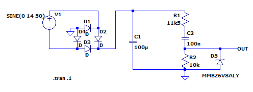
I had a previous thread that was closed (AC Line voltage measurement circuit) where I was trying to build an AC voltage measurement circuit. After having issues with the ZMPT101B, I decided to go back to the basics and just use a transformer as suggested.
I have built this circuit and code, and wanted opinions on it for the AC voltage measurement. I did change from 11.5K to 13.3K on R19.
The following code goes with it:
float getACInVoltage() {
	// Constants
	float ADC_MAX_VOLTAGE = 3.3;  // ESP32's reference voltage
	int ADC_MAX_VALUE = 4095;  // 12-bit ADC
	float ZENER_VOLTAGE = 3.6;  // Voltage clamped by Zener diode
	float DIODE_DROP = 1.4;  // Approximate voltage drop across the rectifier diodes

	// Resistor values
	float R1 = 13300.0;  // 13.3 kΩ
	float R2 = 10000.0;  // 10 kΩ


	// Read the ADC value from the ACINMEASURE pin
        // readSensor is an analogRead of a analog multiplexer
	int adcValue = readSensor(4);

	// Convert the ADC value to voltage
	float vACINMEASURE = (adcValue / float(ADC_MAX_VALUE)) * ADC_MAX_VOLTAGE;

	// Calculate the peak DC voltage before the Zener diode
	float vDC_peak = (R1 + R2) / R2 * vACINMEASURE;

	// Back-calculate the RMS value of the original AC input voltage
	float acInputRMS = (vDC_peak + DIODE_DROP) / sqrt(2);

	return acInputRMS;

}
I'd forget about the Zener as low-voltage Zeners aren't all that precise anyway, and instead just use a Schottky or so to clamp the output to the 3.3V rail like so:
Modify the resistor values to suit your desired measurement range. I simed with the values shown in your circuit and a more or less arbitrary input voltage.
Yes I am just measuring the RMS of the voltage (Outputting Board AC Input voltage for info).
This has been a very tough undertaking that I am about to give up on - I keep running into roadblock after roadblock no matter what method I choose.
@rsmls- thanks for catching that - @jim-p thanks, I never even noticed it looking thru lots of transformers. You guys have helped me out a lot and I appreciate it very much
Basically my requirements is I need a through hole or SMD transformer that is no larger than 15x15mm to fit it into the board space I have. I cannot use a separate AC power brick because it is in a thin enclosure and the brick would not fit - and there is no plug, only direct wire to mains (on a circuit breaker) - I have seen the tiny size transformers they use on those cheap Chinese 120V to 5V supplies, that is what I'm looking for in terms of size, but Digikey and Mouser don't seem to have what I need, and if I find something acceptable, it's either too big or there are no EDA footprints.
Those are all high frequency transformers for SMPS applications.
There are fairly small low-F transformers, but 15x15mm is a really small package. Not sure if you're going to find that. Low frequency @ 120V means the primary coil needs to consist of a pretty large number of windings and that translates to a certain minimum size even if very thin wire is used.
Maybe if you describe the system context a little more it'll be possible to suggest some possible solutions. What do you need to measure the 120VAC (60Hz?) voltage for, at what kind of accuracy, what's being done with the information etc?
@rsmls - I figured they were something special for the SMPS. Thanks.
Sure thing -
This is my first foray into mains measurement. I am building an over-engineered battery charger and power supply that logs all the electrical data, basically. The only reason to have the AC input voltage measurement is just additional information, it's not critical to my project, but it may be for something I do in the future so best to learn now. The accuracy would preferably be within 2-3 volts or better. The schematic and board are finished and breadboard-ed for proofing, except for the AC input voltage measurement. The enclosure this is to fit into hosted a much more basic charger/power supply on a breadboard when I was beginning, that is why I have a maximum PCB size I can use of roughly 216mm x 137mm, and most of the board real estate is taken up.
I am not against using the ZMPT101B, with casual playing with a duplicated circuit it was difficult to get it working correctly, as well as the adjustments it needs, so I abandoned it for the transformer as originally recommended, but it seems the ZMPT101B may be the only method that is compact enough so I may need to hunker down and keep trying...
I would put my experience in the top of the amateur class, I know enough to get most things done (or get in trouble as you can see), but certainly have a long way to go. My father was an electrical engineer who had several patents, I've been playing with the Arduino/ESP stuff for 7 or so years. I have fab'd two other boards that act as a transmitter/receiver of status data that are in a working state in another enclosure using an ATMega1284P.
Since you really don't care what the secondary voltage is, just low. Look for miniature audio transformers that have insulation voltage ratings you need. Any high impedance input winding will work on AC mains.
Personally I'd do either of the following:
1: Try to get that ZMPT101B to work. There's in principle no reason why it couldn't work, so maybe just figure out how to get it right?
2: If you don't like the circuit as such, just remove the transformer from that board and integrate it into your own circuit. This will also make you more flexible w.r.t. spatial planning.
In terms of space, there's some potential for freeing up space by converting most of the components to SMD and revising the layout.
Further space savings can be realized by replacing some of the modules with components you directly include into your circuit. Think of the logic level translator, real time clock module, and perhaps some of the others (text is too small to read; can't quite see what you've got there).
However, don't further reduce spacing around the AC lines. The layout in that area (bottom right section of your board) isn't too abysmal insofar as I can see it, but it doesn't look optimal either. I'd try to keep that area small, and yet stick to healthy spacing of >4mm around AC traces where possible.
I'd also consider including two SMD PTC's as close as possible to the batteries so you have at least a rudimentary way to detect a (gross) overheating scenario.
Coming back to your initial requirement: I'm not sure whether it's so useful to have a reading of line AC voltage. Of course it's up to you to decide, but it's not really actionable data anyway within the scope of this thing you're building, and more of a curiosity kind of thing. In that case, I'd pick any of the easily available power monitor devices off the shelf and have it log your AC voltage. Plenty of them plug right into an AC outlet, connect to WiFi and will log data in whatever way you desire.
@rsmls - thank you for all your suggestions! @Paul_KD7HB I didn't see any on Digikey or Mouser that meet requirements
I was already headed down that path of thinking, I need to be using more SMD components because some of my designs are getting too complex to be using all THT when size is a limiting factor. I agree with the ideas of PTC fuses - I will integrate those.
So, based on everyone's input, it looks like I am going to have to figure out the ZMPT101B after all. I have attached the schematic from the Internet I found. I've noticed at least 1 other variation of this that has different component values. I changed the current resistor to 120K on a recommendation I believe from @jim-p in the other thread. Does this look correct?
That's not what I recommended, although they can be useful, too.
I suggested an NTC (can be PTC, too, but NTC is more common) for temperature monitoring. A PTC fuse isn't going to 'trip' if your battery reaches 80C, but your close-by NTC will pick up the temperature rise just fine so you can intervene in a timely fashion.
You can always use a simulator (e.g. LTSpice) to get a feeling for what it does and how it's supposed to work. Note that the output will be an AC signal biased at 2.5V.
And as said, you could also ignore how they solved the problem and just use the transformer for a variant of the circuit you designed.
Hi,
How accurate do you need the RMS value?
If it is AC, why not just step down the mains, rectify and with a capacitor and analog input measure the Vpeak voltage, then divide by 1.414. KISS.
So, you get an AC signal of around +/-5V.
Then for a rough estimation, as suggested, you could use some kind of peak detector and apply some correction/calibration to get the RMS value. For example:
I'd also consider including two SMD PTC's as close as possible to the batteries so you have at least a rudimentary way to detect a (gross) overheating scenario.
I downloaded LTSpice, but a lot of things are missing like a bridge rectifier, etc. - I searched for symbol downloads but did not come across anything, or libraries - that was a quick search tho I'm sure they are out there.
The Adafruit MCP73833 chargers do have a provision for a NTC -
Chip supports a 10K NTC thermistor which we have stuffed as a plain 10K. For people who require temperature monitors (using high charge rates), remove the 10K and solder in the thermistor in its place
I'll need to look at the Datasheet to see how it is used and functions as a safety measure.
@TomGeorge and @stonemk elaborated to using the ZMPT101B with the original circuit - which makes sense, it isolates it from the mains as I was originally trying to do and is basically a 1:1 transformer, so I threw this together - I was unsure if the sampling resistor was needed - but if this is OK this would solve the problem (alebit with a little more tweaking) - the smoothing caps are in inside the divider so I don't need to use a gigantic 20mm 250V cap.
@jim-p First off, you have been a great help to me and everyone here - thanks so much for being on these forums and sharing your knowledge! You are correct, I could just run the AC directly thru the rectifier and the rest of the circuit if all else fails.