I'm trying to read the engine sensors of an old car (not OBD or similar) with arduino mega. The problem is that the sensors are single-wire and threaded in the engine, so when I want to read a sensor, for example the coolant temperature, I have a constant 12v of the positive and it is the negative that varies the value on the resistance (coolant sensor) giving the voltage that I must interpret with respect to a temperature. So far so good. I have the code worked out and it seems to work fine.
I use a voltage divider to be able to manage the values, and when I try to read only one sensor it seems to work well with arduino (remember that it is the negative that varies), but when I try to read more than one sensor at a time disaster occurs.
Two sensors give two different voltage values varying the negative, that´s right because are different sensors (for example coolant sensor and oil press sensor) but when I connect the voltage divider with the negative to the arduino board, the voltages that should be different from each other are equalized and the reading is not correct.
I tried running the sensors through FZ0430 to see if I could make the voltages independent, but more of the same, having to connect them to the arduino GND the voltage equalizes again.
I've read hundreds of posts in the forums trying to find a possible solution without success.
Sorry not without more information. Post an annotated schematic showing exactly how you have wired it. Be sure to show all connections, power, ground and power sources. Is this going to be in an operating vehicle powered by its electrical system?
Give us the output range of several sensors, that would also help. Also do they change with the battery voltage?
The system is powered by the car's own battery. The battery is connected to the motor and the sensors are original. I have obtained the necessary voltages through the original dashboard of the car. Use the original sensor and the original electrical connectors to obtain the values in volts. (12v from battery and ground from sensor wich is a variable resistor)
This wiring is for one sensor. If I connect mores sensors the ground to arduino is the problem. All the sensors values going to equal. I use a voltage divider to convert the 12volts max of the sensor in 5 volts max for handle with the arduino board
Hi,
I assume the guages that the sensors were connected to battery positive have been removed.
If so you need to include a resistor from the sensor to battery positive to have current flowing through the sensor.
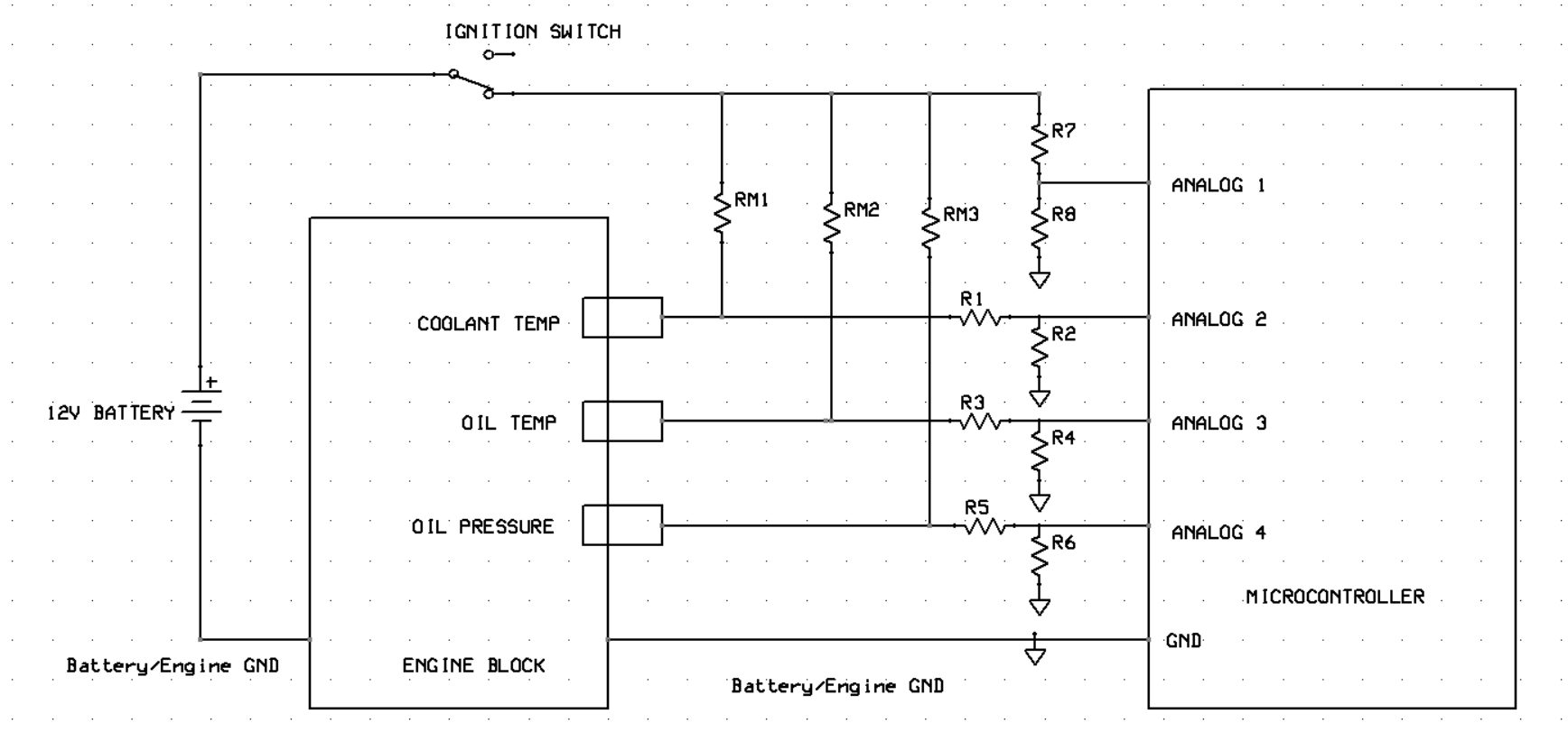
This is a suggestion, open to all who want to add/remove/change elements
The resistors RM are the replacement for the meters.
The potential dividers R1/R2, R3/R4, R5/R6 are to scale down the voltages on the sensor terminals.
The potential divider R7/R8 monitors the battery voltage to help calibrate the other analog inputs as the battery voltage varies from 12 to over 14V.
@paulpaulson your wiring seems conect 12v battery to engine block. In the engine block is the negative of the battery connected already. This proposal not shortcircuit or damage any elements?
@TomGeorge Thanks a lot for your proposal. Looks similar to @paulpaulson with a few variations.
Maybe I don't explain everything well. My plan is to eliminate the original gauges in the car and use an arduino to read the sensors. Then send the information to a nextion screen with the values.
Do you think I still need the RM?. Another question. Maybe my mistake is not having connected the negative of the motor to GND on the arduino, and then connecting the negatives of the voltage divider to negative as well instead of sending them directly to the GND of the arduino?. Could it be?.
I really appreciate your help with this project. I've been working on it for a long time and I still can't get it to work well.
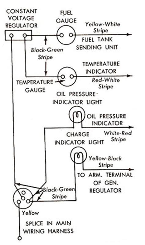
That explains a lot, you are sort of using the Arduino as a power supply. Ground is the reference for all of the measurements and the sensors, they should all be connected together. I found this drawing, and it shows a constant voltage regulator. If my memory is correct the gauges also worked in current mode IE mill amp meters.
For the protection of the sistem I think to use a recycled electronic of on cigarrete mobile charger, because is something very simple and I can suply to it directly from the car to give back 5v., also all the protections are integrated in it.
The value of the resistors of the voltage divider are 1000 ohm and 630 ohm. the value of the gauge resistor is unknow. At the moment I don´t have here the gauge to measure it. As soon as i can take here the gauge I will measure it.
Tomorrow I will make some tests in the breadboard following your electronic suggestions and let you know the progress