This tutorial has an error in RGB pixel control:
docs.arduino.cc/tutorials/nano-33-ble-sense-rev2/cheat-sheet
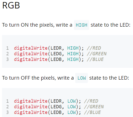
The tutorial has:
But this code running on my BLE Sense Rev 2 shows that logic LOW turns ON the LED pixels.
void setup() {
  // no setup required
}

void loop() {
  // turn all LED pixels ON
  digitalWrite(LEDR, LOW); //RED
  digitalWrite(LEDG, LOW); //GREEN
  digitalWrite(LEDB, LOW); //BLUE
  while(1);
}
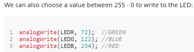
Also, while not an errata, when using analogWrite, a 255 value turns a pixel OFF and a 0 value turns a pixel ON. Not an error in the tutorial, just counter-intuitive.
Thanks for the quick response. Your code performs the same as mine in turning all 3 pixels on.
My point in posting this is that the tutorial is in error in stating the that digitalWrite(LEDR, HIGH); turns the LED pixel on. Rather it is digitalWrite(LEDR, LOW); which turns the pixel on. The logic is inverted relative to the text.
The schematic is the standard, unaltered, BLE Sense Rev 2 board. The LED pixels are on the board. The tutorial is for the BLE Sense Rev 2 board. The point in posting is that the tutorial has a logic error.
I expected the posted code snippet in the tutorial for the BLE Sense Rev 2 board to work as stated. I did not expect the logic error. Hence I was sharing this observation.
Please, my objective here is to communicate what I believe is an error in a tutorial. I am doing this so that others who may be perplexed by why the code snippet is not working as expected have some additional information.
I have every expectation that once I find the Rev 2 schematic the fact that the pixels are ON when a logic LOW is written will make sense. That understanding does not address what looks to be an error in the tutorial.
I see from the schematic that the common leg is +3V3 for DL3.
So that's the technical reason why a logic LOW turns on the pixels.
I apologize for not not clearly stating my intent in this posting which was to correct the tutorial which states that a logic HIGH turns on the pixels.
Now the reason for this situation is explained.
Thank you all for your help.