how can i connect the esp32 with fingerprint sensor GT511C3
this is my code it compiled successfully but the controller restarted
this is the code:
/*
FPS_Enroll.ino - Library example for controlling the GT-511C3 Finger Print Scanner (FPS)
Created by Josh Hawley, July 23rd 2013
Licensed for non-commercial use, must include this license message
basically, Feel free to hack away at it, but just give me credit for my work =)
TLDR; Wil Wheaton's Law
Description: This simple sketch turns the LED on and off similar to the Arduino blink sketch.
It is used to show that communications are working.
This code should work with the any model of ADH-Tech's FPS as long as
you are within the minimum logic level threshold for the FPS serial UART.
This code has been tested with these models:
GT-521F52 [ Fingerprint Scanner - TTL (GT-521F52) - SEN-14585 - SparkFun Electronics ]
GT-521F32 [ Fingerprint Scanner - TTL (GT-521F32) - SEN-14518 - SparkFun Electronics ]
GT-511C3 [ Fingerprint Scanner - TTL (GT-521F52) - SEN-14585 - SparkFun Electronics ]
GT-511C1R [ Fingerprint Scanner - TTL (GT-521F32) - SEN-14518 - SparkFun Electronics ]
*/
#include "FPS_GT511C3.h"
#include "SoftwareSerial.h"
/*-------------------- HARDWARE HOOKUP with 5V Arduino --------------------
1.) Dedicated Bi-Directional Logic Level Converter (LLC)
It is recommended to use a dedicated bi-direcitonal LLC
[ https://www.sparkfun.com/products/12009 ] for a reliable connection if you
are using a 5V Arduino microcontroller:
Fingerprint Scanner (Pin #) <-> Logic Level Converter <-> 5V Arduino w/ Atmega328P
UART_TX (3.3V TTL)(Pin 1) <-> LV1 <-> HV1 <-> RX (pin 4)
UART_RX (3.3V TTL)(Pin 2) <-> LV4 <-> HV4 <-> TX (pin 5)
GND (Pin 3) <-> GND <-> GND <-> GND
Vin (3.3V~6V) (Pin 4) <-> HV <-> 5V
LV <-> 3.3V
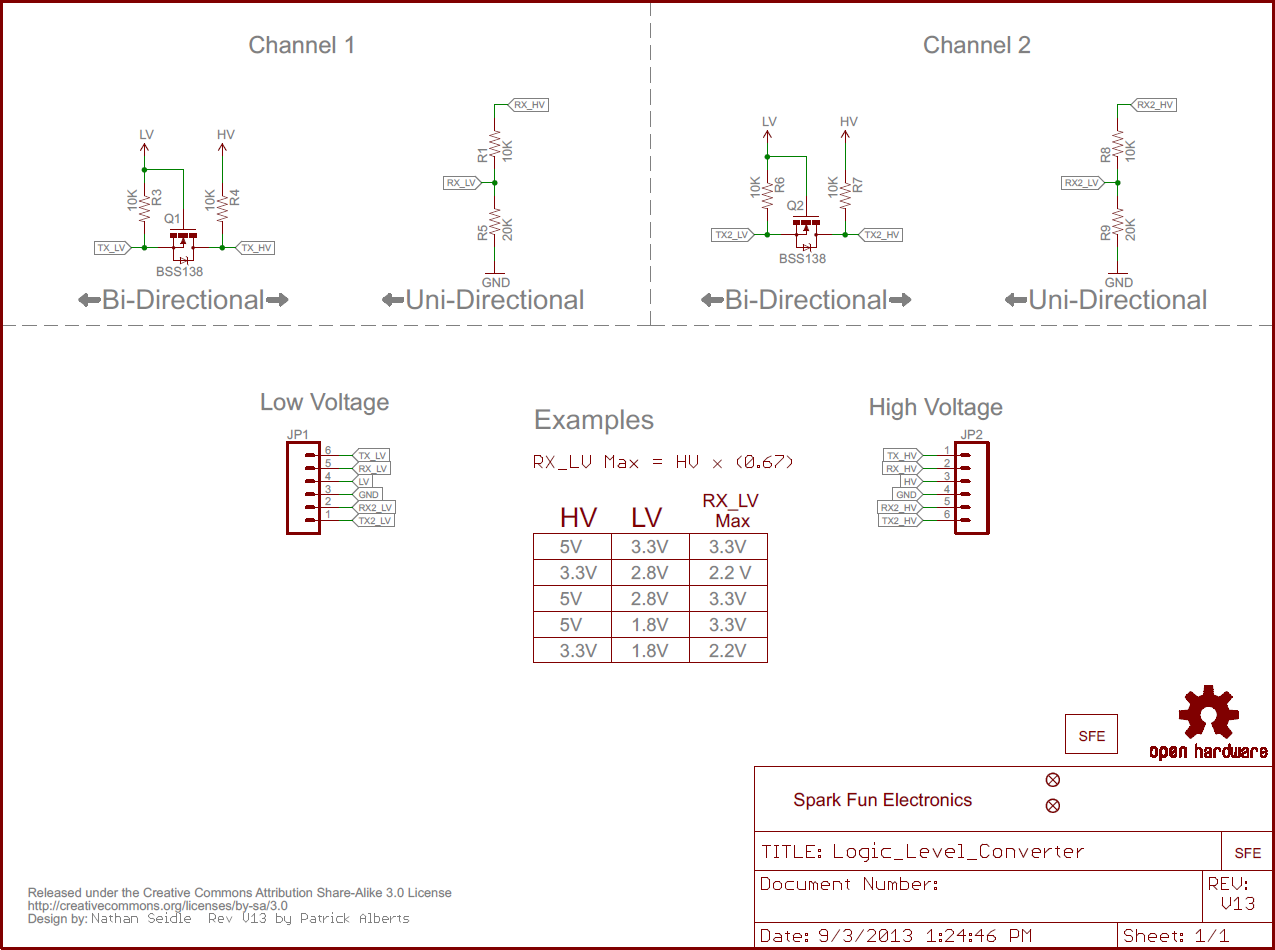
2.) Voltage Division w/ 3x 10kOhm Resistors
Otherwise, you could use 3x 10kOhm resistors [ Resistor 10K Ohm 1/6th Watt PTH - 20 pack - COM-11508 - SparkFun Electronics ]
to divide the voltage from a 5V Arduino down to 3.3V FPS similar to the
"Uni-Directional" application circuit on our old logic level converter
[ https://cdn.sparkfun.com/assets/b/0/e/1/0/522637c6757b7f2b228b4568.png ]:
Voltage Divider <-> Fingerprint Scanner(Pin #) <-> Voltage Divider <-> 5V Arduino w/ Atmega328P
<-> UART_TX (3.3V TTL) (Pin 1) <-> <-> RX (pin 4)
GND <-> 10kOhm <-> 10kOhm <-> UART_RX (3.3V TTL) (Pin 2) <-> 10kOhm <-> TX (pin 5)
GND <-> GND (Pin 3) <-> GND <-> GND
<-> Vin (3.3V~6V) (Pin 4) <-> <-> 5V
Note: You can add the two 10kOhm resistors in series for 20kOhms. =)
--------------------------------------------------------------------------------*/
// set up software serial pins for Arduino's w/ Atmega328P's
// FPS (TX) is connected to pin 4 (Arduino's Software RX)
// FPS (RX) is connected through a converter to pin 5 (Arduino's Software TX)
//FPS_GT511C3 fps(4, 5); // (Arduino SS_RX = pin 4, Arduino SS_TX = pin 5)
/If using another Arduino microcontroller, try commenting out line 59 and
uncommenting line 68 due to the limitations listed in the
library's note => https://www.arduino.cc/en/Reference/softwareSerial . Do
not forget to rewire the connection to the Arduino/
// FPS (TX) is connected to pin 10 (Arduino's Software RX)
// FPS (RX) is connected through a converter to pin 11 (Arduino's Software TX)
FPS_GT511C3 fps(22, 23); // (Arduino SS_RX = pin 10, Arduino SS_TX = pin 11)
void setup()
{
Serial.begin(9600); //set up Arduino's hardware serial UART
//fps.UseSerialDebug = true; // so you can see the messages in the serial debug screen
fps.Open(); //send serial command to initialize fps
Serial.print("111111111");
}
void loop()
{
// FPS Blink LED Test
fps.SetLED(true); // turn on the LED inside the fps
Serial.print("22222222222");
delay(1000);
fps.SetLED(false);// turn off the LED inside the fps
Serial.print("333333333333");
delay(1000);
}