ESP32 core 0 function calling with pvParameters

This is my first attempt to programm a dual core application on a ESP32 DevKit.
My sketch using only the default core is perfectly ok, but I have a function (PulseOut) that should run almost continuosly while the main loop is running to do other stuf, so I though to move the 'PulseOut' function to Core 1.
I studied a number of example on dual core programming and adjusted the code as due, I hope,
These are the relevant code parts:

 //before the Setup
TaskHandle_t PulseTsk;
function declaration according to examples
void PulseOut(void * pvParameters ) { 
...
}
  xTaskCreatePinnedToCore(
    PulseOut,  /* Function to implement the task */
    "PULS",    /* Name of the task */
    10000,     /* Stack size in words */
    NULL,      /* Task input parameter */
    0,         /* Priority of the task */
    &PulseTsk, /* Task handle. */
    0);        /* Core where the task should run */
In the main loop I call the function
        case 5: 
          PulseOut();  // no parameters are required by me

The compilation raises this error:

error: too few arguments to function 'void PulseOut(void*)'

If I change the function declaration in this way, as it was in the original program:

void PulseOut( ) { 

I get this error, referred to the line in xTaskCreatePinnedToCore
PulseOut, /* Function to implement the task */

error: invalid conversion from 'void (*)()' to 'TaskFunction_t' {aka 'void (*)(void*)'} [-fpermissive]

So, my problem is I do not understand what the

void * pvParameters 

in the called function means; in all the examples I saw this is never explained.
Where is my mistake?

It's a parameter that's passed to the task function. That's why the signature is: 'void (*)(void *)'. The parameter is supplied as the 4th parameter of the xTaskCreatePinnedToCore() call.

Hi @orionis ,
You've got a couple of things going on there that you must keep an eye on. Let's start with your question:

You'll be creating a function that will be the executing part of a Task, managed by the scheduler of the RTOS. So you'll have to provide the function in a format RTOS expects, so that it can be placed without problems in its scheduler.
First thing to understand is that you might decide to pass parameters or not to the function, but the TaskCreate has no idea of that, or the kind of parameter you'll be passing, so it expects a (mandatory) pointer as the argument.

A pointer is a pointer, is an address of where the parameters will be placed in memory to be used. Either an integer, a double, an object... the pointer is the address, so the main idea is: you MUST pass a pointer as an argument. NULL is a valid pointer argument, but you must pass one.
The trick here is: in the call you cast the pointer as a VOID type, that means you'll not be telling what kind of element you're pointing to, but you give the address, because that's what RTOS expect to pass.
That's the reaon for the (void * pvParameters ) , you're passing a void*, a not defined, type of pointer.

IF you'll be passing a real useful parameter, the first thing you'll have to do in the callback function is to unravel the type of data you're pointing to. Let's say it is an integer, so you'll have to cast that void* pointer to an int* pointer:
(int*) pvParameters. The (int*) is the notation for casting as an integer pointer, as (char*) would cast it as a char pointer, etc.
To keep the information availabe for the execution of the callback function instead of making the cast once and again the logic next step is to ensure of saving that result in a usable fashion... meaning you'll have to asign the casted pointer to the appropiate type:

int* myDataPointed = (int*) pvParameters

So now the parameters passed are correctly pointed by myDataPointed.

There you tell the parameter you'll be passing is none, that will be placed in your function call, just put a dummy parameter, like in void PulseOut(void* dummy) and do nothing with it in your function.

About the core used, the Core 0 in a dual core ESP32 is the so called Protocol Core, the one running the system, including scheduler, time ticking... you'll be crashing the system. AND if you decide to run that demanding task in core 1, and decide to place other tasks in core 0 to have the core 1 exclusivity... there will be no need to go as extreme as putting it as Priority 0, as there will be NO other tasks competing for the schedule, so you'll have permanent execution in core 1 for that task, no need to go to extremes...

You can see examples of implementations in a library I made for the ESP32

Hope this helps.
Good Luck!
Gaby.//

1 Like

Hei Gaby, you are great :smiley:
Now is a little too late for me so I'll read again your answer and I will look to your library tomorrow.
Just some more suggestion (pls consider my ignorance on the matter):
I have not any parameter to pass to PulseOut (it takes the parameters it needs from some global variables) so, if I understood, I should write something like this:

void PulseOut(void * NULL)

Right?

And now the fundamental point:
I read that Core 1 is where the code is normally executed, while Core 0 does something else, something real dangerous and critical from what you say.
My need is to have the ESP32 (core 1) to handle of the communication with an intelligent display (Nextion) and do some other management tasks.
The MCU-Display dialogue is obviusly asyncronous depending on the user (me) choices; among these there could be the selection of start/stop the PulseOut function that generates a configurated continuos pulse train using internal delays based on micros(). The only way to stop the train is to set a variable (bool running) from the main Loop.

void PulseOut() {
  while (running) {
...
    }
}

Besides this, the PulseOut should not be disturbed nor delayed by any other activity handled by the Loop. This led me to the idea of using the other core (0) to have PulseOut doing its business.

From your quoted sentence, at this late time, is not clear if I can do this without distroyng everything.

A last and small note: I though that Priority 0 is the LOWER priority: why are saying 'no need to go as extreme as putting it as Priority 0' ?
Thanks and good night

Before jumping on Core 0, I'd carefully consider if the job can be done on Core 1 alone by properly using FreeRTOS multi-tasking techniques and inter-process communications / control. Your PulseOut idea using delays is quite crude and subject to variation due to things beyond your control (context switches, interrupts, etc). That job is better accomplished in hardware, perhaps using the ESP32's timers, its RMT, etc.

PS - Core 0 has low-level tasks running on it that, if delayed or perturbed, will cause the ESP32 to crash. Tread carefully.

1 Like

Hi @orionis ,

No, I wouldn't go with that way. No way.
First because by definition the task callbacks expect a parameter, not a constant, to wich the scheduler when it calls it, will asign the value (a pointer) determined by the 4th parameter of your TaskCreate. That's why I told to just put any disposable name to it, and never use it in your task if you don't want to. By your own definition, in the "PULS" task creation, the value passed is NULL. Mission acomplished.
Second, even if it was possible, maybe in a future, when you learn new stuff, you'll find a good use to passing a parameter, you'll want to change your NULL to a real pointer, you go directly to your code, already used to a parameter name (mayby even pvParameters) and... nothing happens? Why? Because you placed a constant where a variable should be placed. You'll mess around and finally find it, not without calling yourself by some unpleasent names!! :slightly_smiling_face:

You're right, sorry, my mistake as I mixed the tasks priority levels with the ints priority levels, and quantity of levels and denominations change from RTOS to RTOS...

You're right about the Priority 0 being the lowest and that also affects the core to use decision: as the core 0 takes care of such important tasks, no task below priority 17 has nearly any chance of getting execution time.

I'll go with @gfvalvo as a final statement: the way to go is with Free-RTOS (ESP-RTOS in this case, as xTaskCreatePinnedToCore is an ESP-RTOS addition to Free-RTOS) multitasking, a producer - consumer classic arrangement, with a nice queue that will unblock the consumer task when it receives data from the producer task...

Then, when you've got the basics running check the stack size. It seems to me very large, maybe as part of your current view of the solution...

Just a little more investigation ahead.

Good Luck!
Gaby.//

1 Like

I hate you :flushed:
The RMT link is really interesting and I MUST study it...that the reason for my hate :grinning:
You and gabygold are giving me real good suggestions that make me cry about my ignorance.
I undestand that I also have firstly to dig into the Free-RTOS; multitasking is something really new to me that I never encountered in the past when working with the PICs.

I already thought to use timers , but since the delays are quickly changing (3 values) inside the function and each timeout could be as low as 10uS I believed it was a challenge to do it.
if interesting, this is my PulseOut routine:

void PulseOut() {
  uint8_t cntPulse = plsNumber;  // plsNumber is the number of pulses to generate
  uint8_t groups = plsGroups;  // plsGroups is how many pulse packets to do (0 means forever)
// plsIdleLevel is the starting level, LOW or HIGH
// plsSpacing is the delay between pulses group

  while (running) {
    digitalWrite(PLS, !plsIdleLevel);  
    usec = micros();
    while (micros() - usec < plsONWidth) { ; }

    digitalWrite(PLS, plsIdleLevel);
    usec = micros();
    while (micros() - usec < plsOFFWidth) { ; }

    cntPulse--;
    if (cntPulse == 0) {
      if (plsSpacing) {
        usec = micros();
        while (micros() - usec < plsSpacing) { ; }
      }
      cntPulse = plsNumber; // reload the pulse counter

      if (!plsForever) { //external plsForever is plsGroups=0
        groups--;
        if (groups == 0) return;
      }

    }  //pulse=0
  }    //running
}  //function

Thanks

1 Like

I don't want to repeat my feeling, as expresse to gfValvo...
The passing parameters is still confusing me. I repeat, I copied the PULS definition as found on the WEB, without really understanding it.
At this point, which is the meaning of this row:

    NULL,      /* Task input parameter */

I understood that the callback function should not expect any parameter, as it is.
but you said:

By your own definition, in the "PULS" task creation, the value passed is NULL. Mission acomplished.

This is not true since the IDE does not compile; should I have to write this:

and the call the function:

void PulseOut(myDataPointed  )

You know, I did not realized that I can use multitasking just inside the single Core 1...another my fault.
BTW, have i to #include something to use it (I did't) or the ESP-RTOS is always available?

The signature of your task function must be 'void (*)(void *)'. You are free to ignore the passed parameter. So PulseOut() should look like this:

void PulseOut(void *param) {
  // Ignore param


}

This screams out for a hardware implementation. I'm highly confident that any software-timed solution you come up with will have far more timing variation (jitter) . The RMT or a DMA-based approach come to mind.

A: These are Reference Documents relating to FreeRTOS:

FreeRTOS_Real_Time_Kernel-A_Hands-On_Tutorial_Guide.pdf (4.4 MB)
FreeRTOS_Reference_Manual_V10.0.0.pdf (2.4 MB)

B: Example of a Multi-tasking Operation
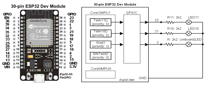
Concurrent (independent) Blinking of Three LEDs

LED (onboard) connected at GPIO-2 will blink at 4-sec interval (2-sec On/2-sec Off).
LED10 connected at GPIO-21 will blink at 2-sec interval (1-sec On/1-sec Off).
LED11 connected at GPIO-22 will blink at 1-sec interval (0.5-sec On/0.5-sec Off).


Figure-1:

After the uploading of the following sketch, it is observed that the above three LEDs are blinking independently (concurrently) at their respective rates. There is only one MCU which is driving three LEDs one after another in a sequential manner. But, the switching from one LED to the next LED is so fast that they appear to be blinking simultaneously. This fast switching arrangement is carried by FreeRTOS (Real Time Operating System) which is automatically loaded into the ESP32’s memory along with the sketch during uploading. There is no timing synchronization among the LEDs.

//function declarations
TaskHandle_t  Task10Handle;
TaskHandle_t  Task11Handle;

//GPIO definitions
#define LED   2
#define LED10 21
#define LED11 22

//task creation using FreeRTOS.h Librray functions
void setup()
{
  Serial.begin(9600);
  pinMode(LED, OUTPUT);
  pinMode(LED10, OUTPUT);
  pinMode(LED11, OUTPUT);

  xTaskCreatePinnedToCore(Task10, "Task-10", 2048, NULL, 1, &Task10Handle, 1);
  xTaskCreatePinnedToCore(Task11, "Task-11", 2048, NULL, 1, &Task10Handle, 1);
}

//LED blinks at 4000 ms interval
void loop()
{
  digitalWrite(LED, HIGH);
  vTaskDelay(2000);
  digitalWrite(LED, LOW);
  vTaskDelay(2000);
}
//LED10 blinks at 2000 ms interval
void Task10(void *pvParameters)
{
  while (true)
  {
    digitalWrite(LED10, HIGH);
    vTaskDelay(1000);
    digitalWrite(LED10, LOW);
    vTaskDelay(1000);
  }
}

//LED11 blinks at 1000 ms interval
void Task11(void *pvParameters)
{
  while (true)
  {
    digitalWrite(LED11, HIGH);
    vTaskDelay(500);
    digitalWrite(LED11, LOW);
    vTaskDelay(500);
  }
}


Figure-2: Task state diagram for Fig-1

1. Execution of Task10()
At time t1 of Fig-2, the MPU1 executes the indicated code (digitalWrite(LED11, HIGH)) to turn On LED11. Why it is LED11 and NOT LED10? When looking into the sketch, it is seen that Task11() (it drives LED11) has been created with higher priority (3); while, Task10() (it drives LED10), loop() and IdleTask() have lower priorities. So, Task11() is executed first.

After that the vTaskDelay(250) code is executed; as a result, the Task11() enters into blocked state and marked as unready in the Ready List of the Scheduler (the Supervisory software that manages orderly execution of the Tasks as planned/scheduled).

A Timer (there are four Timers inside ESP32) is started to count the elapsed time. At time t5 (when 500 ms has elapsed), with the help of a sophisticated mechanism (vectored interrupt or polled interrupt), the Task11() is marked as Ready in the Scheduler's Ready List.

The MPU/Scheduler finds that Task11() is ready to run, and it executes the indicated code (digitalwrite(LED11, LOW) to turn Off LED11. The immediate execution of vTaskDelay(250) puts Task11() into blocked state. At time t7, the LED11 will be turned On again.

The turn On, blocked state, turn Off, and blocked state of Task10() (it drives LED10) can be described exactly in the similar way the Task11() has been described above.

2. Task Switching from Task11() to Task10() (Context Switching)
At the expiry of “Time Slice” period, Task11() has entered into Blocked State at time t2 meaning that Task11() is marked as "unready" in the Scheduler's "Ready List".

The Scheduler checks the “Ready List” and finds that Task10() (recall that all Tasks are in ready states when they are created in the setup() function) is ready for execution. The MPU executes the indicated codes to turn On LED10. However, the following events occur before executing the very first instruction at time t2:

(1) When Task11() was being executed at time t1, the MPU was wholly owned by Task11(). The phrase "wholly owned" refers to the fact that the MPU was using its internal "Register Set" and "Program Counter", etc. to fetch/execute the instructions of Task11().

(2) Because only a tiny part of the program (the Task11()) has been executed, the CPU has produced some intermediate results and statuses (which are now within the registers) must be preserved in order to use them when Task11() will come again in execution phase. Also, the (return) address of the next instruction (to be executed when Task11() comes into execution phase) must also be preserved.

(3) Before control is transferred to Task10(), the Sceduler/MPU saves the intermediate results, statuses, and return address onto stack memory.

(4) After switching, Task10() owns the MPU and its all resources. The registers and program counter are loaded with a different set of values that are relevant to bigin the execution of Tasl10().

3. Execution of loop()

4. Execution of IdleTask()
In Fig-2, it is observed that Task11() has entered into blocked state at time t2; Task110() has entered into blocked state at time t3; loop() task has entered into blocked state at time t4.

The Scheduler checks the Ready List and finds no ready task to execute. What will it do now?

The MPU must do something which is, in the language of FreeRTOS, the creation of an “Idle Task” (IdleTask()) with priority 0 (the most lowest) for execution.

The CPU keeps executing this IdleTask() (spends CPU cycles doing nothing which is same as executing nop (no operation) instruction) until it finds a ready task at time t5.

C: The attached file may worth reading/practicing;
ch-18 ESP32Lec (6).pdf (1.2 MB)

Hi gfvalvo, I tried unsuccesfully your code, after moving the xTaskCreatePinnedToCore to Core 1.

// variable declaration
int* nullPtr =  (int*) 0;
---
// function declaration
void PulseOut(void *nullPtr)   {}
---
// in LOOP
PulseOut(0);

This compile but ther reset continusly (SW_CPU_Reset), boot 13.

I also tried with:

void (*)(void *) PulseOut(* nullPtr) ??

this does not compile: 'expected constructor, destructor, or type conversion before ';' token'

Would you kindly write for me those 3 lines?
Thanks

P.S.
I'm recoding the whole PulseOut function using the timer; unfortunately I first have to know how to call it.

void PulseOut(void *param) {
  
}

void loop() {
  PulseOut(NULL);

}

Hi @orionis,

Yes, the callback function EXPECTS ALWAYS a parameter, a void pointer, when you call the function (actually the RTOS scheduler calls it on your behalf) the value passed might be NULL... The place where you declare wich value will be passed is that 4th parameter in the TaskCreate...

I do believe you're not far away to getting it, but what is missing is just some little background. Not even in a scholar formal way, but some notions about the task creation and the meaning of the parameters. They are pretty easy once you get them.
I think an easier and light way of starting up in just minutes wolud be some videso series on Youtube... let's check...

A light way would be the Shawn Hymel Introduction to RTOS playlist, https://youtu.be/F321087yYy4?si=kGThdScE49XHx3mW

At least for starters... Try them and comment if it makes some more sense than a formal approach!

Good luck.
Gaby.//

Yes, this was almost what I did, and now it is exactly as you wrote, but the results is still:

That looks like a runtime problem, not a compile error. I can't comment on it without seeing the full code.

Ok, I include the code (a little stripped down for similar and unuseful routine).
Thanks
DDS32_03_short.zip (5,7 KB)

Giacomo

Please post the complete code either in the forum with Code Tags or via GitHub. I don't open .zip files of unknown provenance.

@orionis
The following files are extracted from your zip folder of post#17:

DDS32_03_short.ino File

/* 
 =================================================
 Modulo: DDS con ESP32 WROOM e display NEXTION 5"i
 Versione 0.3 - 13/03/24 - freeRTOS
 =================================================
*/
#define VERSION "0.3"
#include <SPI.h>
#include "AD_9833.h"

// Pins assigned
#define ENCA 34
#define ENCB 35
#define ESW 32
#define INS 33
#define INQ 25
#define DAC 26
#define FSY 27
#define SCK 14
#define LEDMKR 12
#define MOSI 13
#define AUXIN1 36
#define AUXIN2 39

#define CSA 15
#define MRK 22
#define PLS 4
#define R2 16
#define T2 17
#define BUZ 5
#define SDA 21
#define SCL 22
#define DS 23
//==========================================

// timing
#define CICLETIME 10                    // Loop cicle timing (mSec)
#define MAXSWEEPTIME 30000 / CICLETIME  //30 sec
#define MARKERTIME 10                   //100mS with timer prescaler set to 80

//fields  parameters
#define NUMMODES 7
#define MODETXTLEN 7

/* other defines */
#define DDS_OFF 0
#define SINE SINE_WAVE          //values from AD9833 library
#define SQUARE SQUARE_WAVE      //values from AD9833 library
#define TRIANGLE TRIANGLE_WAVE  //values from AD9833 library
#define LEDON HIGH
#define LEDOFF LOW
#define BUZZON HIGH
#define BUZZOFF LOW
#define CHANNEL0 0
#define LED LED_BUILTIN

#define POTWRITECOMMAND 0x11
#define MAXPOTLEVEL 200  //not 255, to avoid saturation
#define SQRWAVERATIO 0.16

//=============================================

uint8_t key;  //which key was decoded from keyboard;
uint8_t markerTime;
uint32_t numTicks;
int realWave;

// progran parameters
uint8_t mode, oldMode;
uint8_t wave, oldWave;
uint8_t level;
uint8_t channel;
uint32_t startFreq;
uint32_t endFreq;
uint32_t altFreq;
uint32_t sweepTime;    //define the time (msec) required to complete a sweep
uint16_t plsONWidth;   //in uSec
uint16_t plsOFFWidth;  //in uSec
uint16_t plsNumber;
uint16_t plsGroups;
uint16_t plsSpacing;  //in uSec
uint16_t plsIdleLevel;
uint16_t mrkTime;

//boolean flags
uint8_t running;
uint8_t plsForever;

//calculated values
uint32_t freqSpan;  //difference endFreq and startFreq
uint16_t numSteps;
uint32_t stepFreq;
uint32_t stepTime;
uint32_t currFreq;
uint32_t scanMillis;

//working vars
uint8_t newLevel;
uint8_t dir, levDir;
uint32_t usec;  //generic uS counter used to scan

//arrays
char modes[NUMMODES][MODETXTLEN] = { "FIX\0", "ALT\0", "SCNUP\0", "SCNDW\0", "SCNUD\0", "PULSE\0", "DCO\0" };
char waves[3][5] = { "SIN\0", "TRI\0", "SQR\0" };
uint16_t waveVal[] = { SINE, TRIANGLE, SQUARE };

// Serial handling
const unsigned int MAX_CMD_LEN = 10;  //command lenght
uint8_t cmd = 0;
char cValue[7];
uint32_t nValue;
char msgIn[MAX_CMD_LEN + 1];
char buf[60];

/*------------------------------------------------------------------------------------ */
AD_9833 DDS;  //AD9833 library object
hw_timer_t *Timer0 = NULL;
TaskHandle_t PulseTsk;

void IRAM_ATTR onTimer() {
  timerStop(Timer0);
  digitalWrite(MRK, LOW);
  digitalWrite(LEDMKR, LOW);
  digitalWrite(LED, HIGH);
}

/* ============== Operation functions  ============= */

void FlipMarker() {
  digitalWrite(MRK, HIGH);
  timerAlarmWrite(Timer0, MARKERTIME, true);
  timerAlarmEnable(Timer0);
  timerStart(Timer0);
}

void ResetGenerator() {
  timerStop(Timer0);
  digitalWrite(MRK, LOW);
  digitalWrite(DAC, LOW);
  digitalWrite(BUZ, BUZZOFF);
  digitalWrite(PLS, plsIdleLevel);
  WriteLevel(0);
  PlayDDS(0);
}

//================= Waving functions ========================
void PulseOut(void *param) { // this resets the CPU !!!
  // void PulseOut() { //this gives error: invalid conversion from 'void (*)()' to 'TaskFunction_t' {aka 'void (*)(void*)'} 
  uint8_t cntPulse = plsNumber;
  uint8_t groups = plsGroups;
  Serial.print(" PulseOut is running on: Core_");
  Serial.println(xPortGetCoreID());

  while (running) {
    digitalWrite(PLS, !plsIdleLevel);  //HIGH
    usec = micros();
    while (micros() - usec < plsONWidth) { ; }

    digitalWrite(PLS, plsIdleLevel);  //state=LOW
    usec = micros();
    while (micros() - usec < plsOFFWidth) { ; }

    cntPulse--;
    if (cntPulse == 0) {
      if (plsSpacing) {
        usec = micros();
        while (micros() - usec < plsSpacing) { ; }
      }
      cntPulse = plsNumber;

      if (plsForever == 0) {
        groups--;
        if (groups == 0) break;
      }

    }  //pulse=0
  }    //running
  digitalWrite(PLS, plsIdleLevel);
}  //function


void SweepUp() {
  int cnt;
  Serial.println("Scan UP");
  currFreq = startFreq;
  FlipMarker();
  for (cnt = 0; cnt < numSteps; cnt++) {
    PlayDDS(currFreq);
    currFreq += stepFreq;
    usec = micros();
    while (micros() - usec < 1000 * CICLETIME) { ; }
  }
}

void SweepDown() {
}

void SweepUpDown() {
}


/* =============== <AD9833 functions =============== */
void PlayDDS(uint32_t thisFreq) {
  DDS.setFrequency(realWave, (float)thisFreq);
}

void WriteLevel(int v) {  //0..255
  int realV;
  realV = map(v, 0, 100, 0, MAXPOTLEVEL);
  SPI.beginTransaction(SPISettings(4000000, MSBFIRST, SPI_MODE0));
  digitalWrite(CSA, LOW);
  SPI.transfer(POTWRITECOMMAND);  //write command byte for 1st channel
  SPI.transfer(realV);
  digitalWrite(CSA, HIGH);
  SPI.endTransaction();
  delayMicroseconds(5);
}

/* ================================================= */
void setup() {
  pinMode(LED, OUTPUT);
  pinMode(CSA, OUTPUT);
  pinMode(FSY, OUTPUT);
  pinMode(BUZ, OUTPUT);
  pinMode(MRK, OUTPUT);
  pinMode(PLS, OUTPUT);
  pinMode(INS, OUTPUT);
  pinMode(INQ, OUTPUT);
  pinMode(DAC, OUTPUT);
  pinMode(LEDMKR, OUTPUT);

  pinMode(ENCA, INPUT);
  pinMode(ENCB, INPUT);
  pinMode(ESW, INPUT);
  pinMode(DS, INPUT);

  //init vars
  running = 0;
  mode = 4;
  oldMode = 99;
  wave = 0;
  oldWave = wave;
  level = 60;
  startFreq = 400;
  endFreq = 4000;
  altFreq = startFreq;
  sweepTime = 2000;
  plsIdleLevel = LOW;
  plsNumber = 4;
  plsGroups = 0;
  plsOFFWidth = 250;
  plsONWidth = 250;
  plsSpacing = 500;
  plsForever = 0;
  channel = CHANNEL0;
  realWave = waveVal[wave];
  mrkTime = MARKERTIME;

  digitalWrite(CSA, HIGH);
  digitalWrite(FSY, HIGH);
  digitalWrite(PLS, plsIdleLevel);

  Serial.begin(115200);
  delay(1000);

  //initiate the devices
  SPI.begin(SCK, -1, MOSI, -1);
  delay(100);
  DDS.begin(FSY);  //includes SPI.Begin !!!
  delay(100);
  Timer0 = timerBegin(0, 50000, true);  //50 mSec
  timerAttachInterrupt(Timer0, &onTimer, true);
  timerAlarmWrite(Timer0, mrkTime, false);  //100 mSec - no autoreload

  //Tasks
  xTaskCreatePinnedToCore(PulseOut, "PULS", 1000, NULL, 1, &PulseTsk, 1);

  ResetGenerator();
  delay(100);
}


void loop() {
  uint8_t inByte, ln, ch;
  static uint8_t message_pos = 0;
  static char message[MAX_CMD_LEN + 1];
  static uint8_t flip = 1;
  static uint8_t tostop = 0;


  while ((millis() - scanMillis) < CICLETIME) {  //wait for CICLETIME timeout
    while (Serial.available() > 0) {
      char inByte = Serial.read();

      if (inByte != '\n' && (message_pos < MAX_CMD_LEN)) {
        message[message_pos] = inByte;
        message_pos++;
      } else {
        message[message_pos] = '\0';
        nValue = 0;
        for (ln = 0; ln < message_pos; ln++) {
          ch = message[ln];
          if (ln == 0) {
            if (ch >= 'a' && ch <= 'z') ch -= 0x20;
            if (ch < 'A' && ch > 'Z') return;
            cmd = ch;
          } else {
            nValue = 10 * nValue + (ch - '0');
          }
        }
        doCommand();
        message_pos = 0;
      }
    };
  };
  scanMillis = millis();

  if (running) {
    tostop = 1;

    if (mode != oldMode) {
      oldMode = mode;

      switch (mode) {
        case 0:  //FIX
          WriteLevel(level);
          PlayDDS(startFreq);
          break;
        case 1:  //ALT
          break;
        case 2:  //SCNUP
          freqSpan = endFreq - startFreq;
          numSteps = sweepTime / CICLETIME;
          stepTime = sweepTime / numSteps;
          stepFreq = freqSpan / numSteps;
          WriteLevel(level);
          SweepUp();
          running = 0;
          tostop = 1;
          break;
        case 3:  //SCNDW
          freqSpan = endFreq - startFreq;
          numSteps = sweepTime / CICLETIME;
          stepTime = sweepTime / numSteps;
          stepFreq = freqSpan / numSteps;
          WriteLevel(level);
          SweepDown();
          running = 0;
          tostop = 1;
          break;
        case 4:  //SCNUD
          freqSpan = endFreq - startFreq;
          numSteps = sweepTime / CICLETIME;
          stepTime = sweepTime / numSteps;
          stepFreq = freqSpan / numSteps;
          WriteLevel(level);
          SweepUpDown();
          running = 0;
          tostop = 1;
          break;
        case 5:  //PULSE
          plsForever = (plsGroups == 0);
          PulseOut(NULL);
          tostop = 1;
          break;
        case 6:  //DCO
          break;

        default:
          break;
      }
    }
  } else {
    if (tostop) {  //reset the generator
      ResetGenerator();
      tostop = 0;
      oldMode = 99;
    }
  }
}

void doCommand() {
  uint8_t v;
  switch (cmd) {
    case '0':
      running = 0;
      break;
    case '1':
      running = 1;
      break;
    case '2':
      SweepUp();
      break;
    case '3':
      SweepDown();
      break;
    case 'M':
      if (nValue < NUMMODES) mode = nValue;
      break;

    case 'L':
      level = nValue;
      Serial.print("New level = ");
      Serial.println(level);
      WriteLevel(level);
      break;
    case 'F':
      startFreq = nValue;
      Serial.print("New frequency = ");
      Serial.println(startFreq);
      PlayDDS(startFreq);
      break;
    case 'E':
      if (nValue <= startFreq) return;
      endFreq = nValue;
      Serial.print("New endFrequency = ");
      Serial.println(endFreq);
      PlayDDS(startFreq);
      break;
    case 'W':
      if (nValue < 3) {
        wave = nValue;
        if (wave != oldWave) {
          if (wave == 2) level *= SQRWAVERATIO;  //Note: SQRWAVERATIO is < 1
          if (oldWave == 2) level /= SQRWAVERATIO;
        }
        realWave = waveVal[wave];
        oldWave = wave;
        Serial.print("New wave = ");
        Serial.print(waves[wave]);
        Serial.print("\tNew level = ");
        Serial.println(level);
      }
      break;
    case 'P':
      if (nValue < MAXSWEEPTIME) sweepTime = nValue;
      break;

    case 'N':  //number of pulses
      plsNumber = nValue;
      Serial.print("Pulses = ");
      Serial.print(plsNumber);
      break;
    case 'U':  //time UP
      plsONWidth = nValue;
      Serial.print("Pulse On (us) = ");
      Serial.print(plsONWidth);
      break;
    case 'D':  //time UP
      plsOFFWidth = nValue;
      Serial.print("Pulse Off (us) = ");
      Serial.print(plsOFFWidth);
      break;
    case 'G':  //time UP
      plsGroups = nValue;
      Serial.print("Groups = ");
      Serial.print(plsGroups);
      break;
    case 'S':  //spacing
      plsSpacing = nValue;
      Serial.print("Spacing = ");
      Serial.print(plsSpacing);
      break;
    case 'I':
      plsIdleLevel = !plsIdleLevel;
      break;
    case 'K':
      markerTime = nValue;
      Serial.print("Marker Time = ");
      Serial.print(markerTime);
      timerAlarmWrite(Timer0, markerTime, true);  //100 mSec - no autoreload
      break;

    default:
      break;
  }
}

AD_9833.h File

#ifndef __AD_9833__
#define __AD_9833__

#include <Arduino.h>
#include<SPI.h>

//Pre-defined commands from the datasheet
#define CMD_RESET         0x100
#define CMD_FREQ0_WRITE   0x4000
#define CMD_FREQ0_OUTPUT  0x800
//These are the supported waveform types:
#define SINE_WAVE         0x2000
#define TRIANGLE_WAVE     0x2002
#define SQUARE_WAVE       0x2028

class AD_9833 {
public:
	AD_9833();

	void begin(uint8_t funcPin);

	void setFrequency(uint16_t waveType, float freq);

	void reset();

private:
	void sendControlCommand(uint16_t waveType);

	void sendCommand(int16_t cmd);
};

#endif

AD_9833.cpp File:

#include "AD_9833.h"

/**
* This is a class to provide basic functionality of the AD9833
* function generator. This class only provides frequency and
* waveform control of a single register to keep code base small.
*/
AD_9833::AD_9833() {}


//Global variables
uint8_t funcPin = 10;

/*
* Initialisation function to set up communication and begin
* using the device. This must be called first, before anything
* else will work.
*/
void AD_9833 ::begin(uint8_t fPin) {
  /*Set the function pin to output.
	* This controls SPI communication with the
	* chip. Active LOW.
	*/
  funcPin = fPin;
  pinMode(funcPin, OUTPUT);
  digitalWrite(funcPin, HIGH);

  //Begin SPI communication
  SPI.begin();

  //Short delay and reset required by the device
  delay(100);
  reset();
}

/*
* Calculates and applies a frequency to the FREQ0 register.
* Because both double, long, and float are all 4 bytes long
* we will measure everything in kilohertz to allow the higher
* frequency ranges to be selected.
* Waveforms can be of the type SINE_WAVE, SQUARE_WAVE, or 
* TRIANGLE_WAVE.
*/
void AD_9833 ::setFrequency(uint16_t waveType,  float freq) {  //MODIFICATA
  /*
	* According to the datasheet:
	* f = (clk / 2^28) * FREQREG
	*
	* 2^28 = 268,435,456
	* The clock frequency is 12.5MHz so FREQREG  
	* will always equal f * (2^28 / 12,500,000) = 21.47483648
	//MODIFICATA
	* The clock frequency is 25MHz so FREQREG  
	* will always equal f * (2^28 / 25,000,000)
	*/

  //Pre-calculated magic number because the full numbers don't fit in 4-byte LONGs.
  // float clock_multiplier = 2684356 / 250000;
  // ovvero:  268,435,456 / 250000 ) = 10,73741824 = circa 10.74

  float clock_multiplier = 10.73741824;
  // float clock_multiplier = 21.47483648;
  uint32_t REG_value = (uint32_t)((freq * clock_multiplier) * 1);
  // uint32_t REG_value = (uint32_t)((freq * clock_multiplier));

  //Split in two MSB and LSB
  // int16_t FREQ_MSB = (int16_t)((REG_value) >> 15);
    int16_t FREQ_MSB = (int16_t)((REG_value & 0xFFFC000) >> 14);
  int16_t FREQ_LSB = (int16_t)(REG_value & 0x3FFF);

  //Combine with the command to write to FREQ0 register
  FREQ_MSB |= CMD_FREQ0_WRITE;
  FREQ_LSB |= CMD_FREQ0_WRITE;

  //Send commands
  sendControlCommand(waveType);
  sendCommand(FREQ_LSB);
  sendCommand(FREQ_MSB);
}

/*
* Send the reset command to the chip.
*/
void AD_9833 ::reset() {
  sendCommand(CMD_RESET);
}

/*
* Sends the initial control command to prepare the
* chip to receive frequency information. This will
* also update the waveform.
* (Other features can be implemented here if
* required)
*/
void AD_9833 ::sendControlCommand(uint16_t waveType) {
  uint16_t cmd_reg = 0;

  //OR together all the options that we want
  cmd_reg &= ~CMD_FREQ0_OUTPUT;  //Use FREQ0 register for output
  cmd_reg |= waveType;           //set sine wave form
  cmd_reg &= ~CMD_RESET;         //Remove the reset bit to enable output

  //Send the command
  sendCommand(cmd_reg);
}

/*
* Sends a pre-written command to the control register
* of the AD9833 chip.
*/
void AD_9833 ::sendCommand(int16_t cmd) {
  //Enable SPI transmission
  SPI.setDataMode(SPI_MODE2);

  //Set the function pin to LOW (active)
  digitalWrite(funcPin, LOW);

  //Send MSB first, LSB second
  SPI.transfer(highByte(cmd));
  SPI.transfer(lowByte(cmd));

  //Set the function pin inactive
  digitalWrite(funcPin, HIGH);
}

Thanks.

@orionis, that's a huge problem. It's a fundamental rule of FreeRTOS that once a task's function is kicked off, it must NEVER be allowed to return. There must be an infinite loop.

There's also a likely data race problem with the variable 'running' being accessed from both the PULS task and the task running 'loop()'.

You must stop and go no further until you've studied the basics of task management in FreeRTOS.

1 Like