ESP32 Float Switch

I would appreciate it if someone could help point me in the right direction. For context, my electronics and microcontroller knowledge is mostly limited to dabbling and following guides albeit programming is a stronger area for me. I will try and keep this as brief as possible.

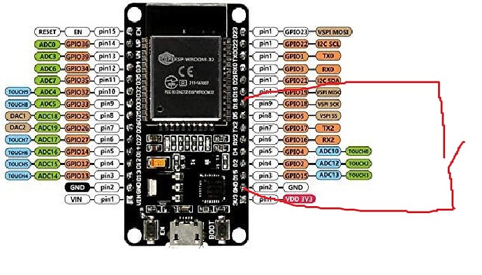
I wanted to achieve what I perceived would be a fairly simple project, an ESP32 acting as a web server to serve the value/state of a float switch. I grabbed an unbranded ESP-32S, connected a float switch (chunky sewage style one on an unshielded 5m cable) and connected it to ground and Pin 18, wrote my code to set the pin to INPUT_PULLUP and perform digital reads on the pin when requested.

Very brief testing on the desk worked well, so (given I was trying to solve an issue) I deployed it into use. I am grabbing a reading from the web-page every 1.5 minutes. A few hours after install, the float switch floated. What I observed was periods of several minutes (ranging say 5 - 45) where I was receiving the expected value (0) from the digitalRead punctuated with individual reads of an unexpected value (1). Initially I chalked this up to turbulence in the water causing the switch to change.

Some time later, the float switch stopped floating, and I received several hours of expected values (1), punctuated with the very occasional unexpected value (0) which was not caused by the switch as it is suspended in free air.

I started to wonder whether I would need to de-bounce the switch which I hadn't previously done because I thought my periodic checks wouldn't really suffer from bouncing. Before I could consider implementing this, my digitalRead started to read 0 again, this time however, there is still no chance of the switch floating (double checked with resistance on multimeter) and the digitalRead has just been stuck returning 0 through resets.

I have now moved to another pin, and I am working again, albeit obviously expecting the above to happen again.

I have several thoughts on what my issues could be, but not really enough knowledge to know whether they apply.

  • 5m unscreened cable, perhaps interference of some kind, there was a coiled up (and powered) extension cable nearby, not sure if that could cause interference enough to give sporadic results (and perhaps kill the pin)?
  • Using internal pullup resistors, especially over a longer cable, I have seen some suggestions that with a longer cable an external resistor might be more appropriate?
  • Bad luck? A dodgy pin or microcontroller?
  • Other things I have not come across?

Any help would be really appreciated here, I am totally happy to research and learn, but feel I might benefit from somebody more experienced to point me in the right direction.

Thanks in advance.
Welcome to the forum

Please post your sketch, using code tags when you do, and a schematic of your project

1 Like
/*********
  Rui Santos
  Complete project details at https://randomnerdtutorials.com  
*********/

// Import required libraries
#include "WiFi.h"
#include <ESPAsyncWebSrv.h>

//Adafruit_AHTX0 aht;

// Replace with your network credentials
const char* ssid = "xxxx";
const char* password = "xxxxx";

const int floatSwitchPin = 21;
String deviceName = "xxxx";

// Create AsyncWebServer object on port 80
AsyncWebServer server(80);

const char index_json[] PROGMEM = R"rawliteral(
{"deviceName":"%DEVICENAME%","floatSwitch":"%FLOATSWITCH%"})rawliteral";

const char index_html[] PROGMEM = R"rawliteral(
<!DOCTYPE HTML><html>
<head>
  <meta name="viewport" content="width=device-width, initial-scale=1">
  <style>
    html {
     font-family: Arial;
     display: inline-block;
     margin: 0px auto;
     text-align: center;
    }
    h2 { font-size: 3.0rem; }
    p { font-size: 3.0rem; }
    .units { font-size: 1.2rem; }
    .dht-labels{
      font-size: 1.5rem;
      vertical-align:middle;
      padding-bottom: 15px;
    }
  </style>
</head>
<body>
  <h2>xxxx</h2>
  <p>
    <span class="dht-labels">Float Switch</span> 
    <span id="temperature">%FLOATSWITCH%</span>
  </p>
</body>
</html>)rawliteral";

// Replaces placeholder  values
String processor(const String& var){  
  if(var == "FLOATSWITCH"){
    return String(digitalRead(floatSwitchPin));
  }
  else if(var == "DEVICENAME"){
    return deviceName;
  }
  return String();
}

void setup(){
  // Serial port for debugging purposes
  Serial.begin(115200);

  pinMode(floatSwitchPin, INPUT_PULLUP);

  IPAddress local_IP(10, 40,xxx,xxx);
  IPAddress gateway(10, 40, xxx, xxx);
  IPAddress subnet(255, 255, 255, 0);
  IPAddress primaryDNS(8, 8, 8, 8);   //optional
  IPAddress secondaryDNS(8, 8, 4, 4); //optional

// Configures static IP address
  if (!WiFi.config(local_IP, gateway, subnet, primaryDNS, secondaryDNS)) {
    Serial.println("STA Failed to configure");
  }

  WiFi.setHostname(deviceName.c_str());
  WiFi.begin(ssid, password);
  while (WiFi.status() != WL_CONNECTED) {
    delay(1000);
    Serial.println("Connecting to WiFi..");
  }

  // Print ESP32 Local IP Address
  Serial.println(WiFi.localIP());

  // Route for root / web page
  server.on("/", HTTP_GET, [](AsyncWebServerRequest *request){
    request->send_P(200, "text/html", index_html, processor);
  });

  server.on("/json", HTTP_GET, [](AsyncWebServerRequest *request){
    request->send_P(200, "application/json", index_json, processor);
  });

  // Start server
  server.begin();
}
 
void loop(){
  
}

I tried to do the schematic on one of the online platforms, but taking a while for such a simple circuit, so please forgive this terrible piece of art!!

3 hours in to using a new pin, and I have seen my first random blip with the pin reading 0 for one reading, so I am assuming the rest of the pattern will repeat. The only differences this time is that I have removed the coiled extension cable from the equation and am using pin 21

Without looking at the code, my money would be on that one.

As you don't need to respond to fast transitions in the switch state, I'd stick a 100nF capacitor between ESP32 ground and the ESP32 pin that's reading the sensor.

If that didn't fix it, I'd consider a bigger capacitor and an external pull up resistor of 1k Ohms. 1k would be an extra 3.3 mA draw from the 3.3V supply when the sensor switch was closed. That shouldn't matter, unless you want to put the ESP32 into low power mode.

2 Likes

Thanks for taking the time to read and respond @Dave_Lowther I will look to try this and see what results I get. When you mention the bigger capacitor if it doesn't fix it, could you steer me regarding the rating you would try?

Perhaps the 9 volt battery is dying?

1 Like

Thanks for the response @Paul_KD7HB it isn't battery powered, but I did omit to include the power details so thank you. It is powered via a mains to USB adapter rated to 1 amp.

Sure.

I didn't look through the code for some error which may cause the irregular symptoms you are seeing. I wouldn't do that immediately for my own code either, I'd suspect noise from a switch on 5m of cable with no filtering.

You could filter in software, e.g. require N readings of the same value over several seconds before you accept the input value, but that feels a bit like "a rubber glove to fix a leaky pen" type solution.

FWIW: I have a reed switch sensor on a humane rodent trap in my loft. When the door of the trap closes the reed switch opens, which causes the ESP32 to send me an e-mail. That's about 10m of screened twisted pair. I put a 100nF across the ESP32 end of the switch as part of the initial build. I've never had a problem in false triggering since installing it a few years ago. I happened to have a reel of screened twisted pair, that's why I chose to use it. I'm not saying it's necessary to use it.

1 Like

This is the pinout for a generic ESP32S
Doesn't match what you show.
Sure you are connected to the pins you think you are connected to?

Maybe you don't have a ESP32S

1 Like

Thank you @Dave_Lowther your thorough response and guidance on approach to problem solving it is much appreciated.

Thanks for a good question @jim-p the model I have quoted is grabbed from the Amazon listing (just a cheap unbranded one), and the associated image on the page did match the pin labelling of my device.

As to the question "Am I sure?", I satisfied myself at initial setup by getting the correct results when manually tipping the float switch up, however, what I have been reading about floating pins and the many things that can influence them, I guess I shouldn't rule out a coincidence / circumstance whereby tipping the switch connected to a wrong pin influenced the pin I was listening to. I guess the best way to be 100% sure here would be to make it an output pin and measure the results with a multimeter?

From more that 15 years using float switches with my irrigation system. Water from domestic well to storage tanks.
Once you get a single indication from a float switch never continue to read the switch until needed some time later. Since you have a single float switch, wait to read again until the water has time to drain away. In my case once the tank is full I don't read the full switch again until the bottom float switch tells me more water is needed. Then ignore the bottom switch until the top shows a full tank.

1 Like

The internal microcontroller pullups/pulldowns are very weak and intended for contacts that are nearby, like pushbuttons on the same PCB. If you're going to run a signal 5m, I'd use a pull up resistor no larger than 4.7k. A 0.1uF cap in parallel wouldn't hurt, either.

2 Likes

@Dave_Lowther thank you for your patience with an experienced person! I had a chance to dig through my box of tricks yesterday as I thought I had a box of capacitors in there, which indeed I did. However, my capacitors are Electrolytic, which I think might not be good for the job as they are polarity specific?! Should I be looking at a different type of capacitor, or do I just need to attach it in a certain polarity? Thank you for your help with this.

An electrolytic capacitor may work. You must connect the positive pin of the capacitor to the ESP32 input pin, and connect the negative pin to ESP32 ground. There is no need to worry about the capacitor's voltage rating, because it will be higher than 3.3V. I'd use a low value in the 1uF-10uF range. If you don't have one that low then use the lowest one you have.
Electrolytic capacitors aren't as good as ceramic capacitors for filtering high frequency noise. If I were you I'd try a low value electrolytic and order some 100nF ceramic capacitors anyway. They are useful things to have in the spares box.
[Edit added the following text]
You may need a delay after setting the input pin to INPUT_PULLUP and before reading the sensor value. The 20k ohm internal pullup will take some time to charge up the capacitor. You can find out more about the time taken to charge the capacitor using this calculator.


For the above example, the time constant is 200ms. Waiting 3 x time constant (600ms in this case) would be fine. See the charging graph on the calculator page.

1 Like

The best way would be to find the correct pinout diagram for the ESP board you have and select the correct board in the Arduino IDE. That should dispel any doubts about using the wrong pin
Also you should use the GPIO number in your code, not pin numbers.

1 Like

@Dave_Lowther thank you so much again, a selection of ceramics are on order and I am testing (short cable only at the moment) with the capacitor in place.

@jim-p thank you, I am fairly certain the diagram I have IS correct, or at least it was in the product description of and has the same labelling as my board. That said, perhaps I will try and get a bit more discerning with the boards I buy, and where I buy them from.

Thanks for the advice about using the GPIO number rather than the pin number, and also about selecting the right board in the IDE, I will read up some more on this to increase my understanding.