Good day guys & gals,
Ive been working to interface an A02YYUW Ultrasonic sensor with my ESP32. The RX/TX pins are connected to Pins 12 and 14, and I cannot change this in order to use Hardware serial, so i've been trying to make SoftwareSerial work.
The issue I'm having is, that my UART readout is 255 for all of the 4 bits. As such, I am not getting a good reading from the sensor. I've verified my connections to the best of my abilities, so I suspect it's a code issue. Any help in this manner would be appreciated. Thanks!
// Import required libraries
#include <Arduino.h>
#include <SoftwareSerial.h>
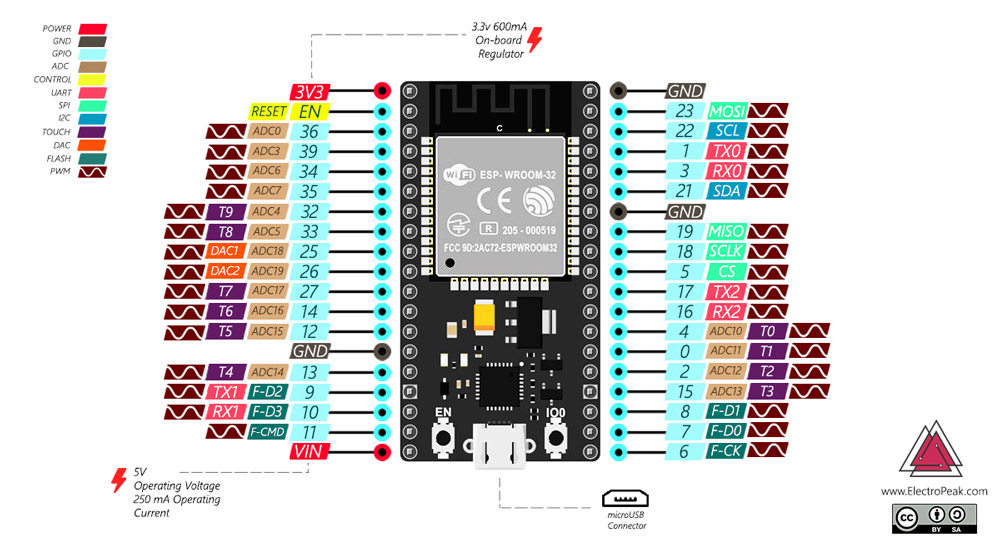
#define MYPORT_TX 12
#define MYPORT_RX 14
unsigned char data[4]={};
float distance;
EspSoftwareSerial::UART myPort;
void setup()
{
Serial.begin(115200); // Standard hardware serial port
myPort.begin(9600, EspSoftwareSerial::SWSERIAL_8N1, MYPORT_RX, MYPORT_TX, false);
if (!myPort) { // If the object did not initialize, then its configuration is invalid
Serial.println("Invalid EspSoftwareSerial pin configuration, check config");
while (1) { // Don't continue with invalid configuration
delay (1000);
}
}
}
void loop() {
do{
for(int i=0;i<4;i++)
{
data[i]=myPort.read();
}
}while(myPort.read()==0xff);
Serial.print("Data 0 =");
Serial.println(data[0]);
delay(500);
Serial.print("Data 1 =");
Serial.println(data[1]);
delay(500);
Serial.print("Data 2 =");
Serial.println(data[2]);
delay(500);
Serial.print("Data 3 =");
Serial.println(data[3]);
delay(500);
if(data[0]==0xff)
{
int sum;
sum=(data[0]+data[1]+data[2])&0x00FF;
if(sum==data[3])
{
distance=(data[1]<<8)+data[2];
if(distance>30){
Serial.print("distance=");
Serial.print(distance/10);
Serial.println("cm");
}
else
{
Serial.println("Below the lower limit");
}
}else Serial.println("ERROR");
}
myPort.flush();
delay(500);
}
but you can define any pins as a hwSerial pair. Mind you, those particular pins may cause some issues, but how about you just try to use them for UART2
I did not know this. I thought HW serial was limited to pins 1&3 as seen below, however i tried to compile as you suggested and did not get any issues.
By default TX0 & RX0 are 1 & 3, but those are also the pins that the USB to TTL interface is connected to, resulting in no reception on the RX pin, so if you'd want to use UART0 without USB, you should already re-define those pins. UART2 has 17 & 16 by default, that actually works on those pins.
UART1 has pins 9 & 10, but those are also used by the flash, and not recommended (causes a run-time error)
so those should be re-defined if you want to use that UART.
Just wondering now, if i set both GPIO 1 & 3 to 'INPUT' one should be able to connect to the USB-TTL while bypassing the ESP's UART, but this is of course a completely different matter.
Thank you for the insight. I was under the misconception that the UART pins (all 3 sets) were rigid and could not be reassigned, however, it is very useful to see that this is not the case.
Im not exactly sure what you mean by this, but will look into the .available() command to see if i can improve. That section of the code was shamelessly copied from the DF robot example as a (theoretically) "working" starting point.
EDIT: @Delta_G, Would this be an appropriate implementation of the myPort.(available) as you sugested?
  // reply only when you receive data:
  if (myPort.available() == 4) {
    // read the incoming bytes:
    data[] = Serial.read();
I tried this, and still no reading. Interesting to see that now all bits are 0 instead of 255. Ive verified the HW wiring (TX, RX, GND all good, sensor receiving 3.4V) And trying to probe with the oscilloscope now.
Again, want to thank you @Delta_G for your time and effort in this manner
those 2 ms we can spare, reception of a byte at 9600 takes just over 1 ms.
What i did forget (and you missed as well)
if (i == 4) { // only then was the transmission complete, otherwise you may still be looking at old data.
That can be done in your method as well (just to be clear, yes my code is blocking in a sense, but this is not the issue the OP is having, it can be optimized later once reception has been confirmed)
Keep in mind that you are transmitting more bytes than you are receiving and although you are transmitting at a higher speed, you transmit up to 10 bytes for every byte received + the notification) Once the TX buffer is full, Serial.print() becomes blocking automatically (basically the program will wait until there is space in the TX-buffer) So you debug code is just as blocking as mine.
btw. Thanx for the help though.
@zach3d How about first you verify that those pins are actually working as a tx/rx pair by sending Serial data from the TX pin (and receive them with a different device i guess you will have an arduino lying around somewhere) and receive from the RX-pin and send that output to the USB-serial.
Serial.println("Got some serial data!");
    // read the incoming bytes:
    for(int i = 0; i<4; i++){
        data[i] = myPort.read();
        Serial.print("data[");
        Serial.print(i);
        Serial.print("] = ");
        Serial.println(data[i]);
'data[x] = x (or xxx) \n'
that is between 11 & 13 bytes * 4 + 'Got some serial data'\n
so reception does take time, but for every 4 bytes you send 65 byes or so, filling up the TX buffer completely. Speed wise you will be on par input to output more or less, (given that 9600 * 12 = 115200) but the 16 byte header will cause the TX buffer to overflow if the data stream is continuous, after 4 iterations already..
Anyway it is all very unimportant.
that is so true.
Yes of course, and then all the work starts.
he (that is actually an assumption) will want his code to work using those pins, i should really just quickly check to see if it does on one of my ESp32's I have the facilities set up.
I got all that, but, so was i,... just making sure something should come out. I use the 'if (!Serial.available()) delay(1);' method a lot when dealing with data streams with an unknown (or variable) length. (basically, 'oh something has come in, let's wait and see the complete message. Like waiting next to the fax machine the moment it starts producing the message.)
Anyway on a different point. Pins 12 & 14 should do the trick just fine, i assigned Serial2 to them and have reception and transmission. So just assuming that the hardware is connected properly, what is being sent ?
I did not actually. I just understood that the Header bit from the sensor was supposed to be 0xFF (or 255, according to my hexa-to-decimal conversion lol).
I will try this tonight when i get back home.
This is a great idea, I will also try this if all else fails.
I really appreciate you going through the effort the verify this independently. I wish i could answer your question. I will update you when i have tested further, and in the meantime, any other ideas are very much appreciated.
Regarding the efficiency of the code (as discussed above), At this point all i'm aiming for is to get it working. However, any feedback for keeping the code robust and efficient is appreciated as it gives me pointers of good practice after the communication is established.
Just had another look at the datasheet, so just to make sure, you are powering the sensor with 3.3v, that would mean that there is no need to modify the logic level.
Now the TX & RX lines need to be crossed over. TX ESP -> RX sensor & TX sensor -> RX ESP
I personally have resorted to using lines with a 1K resistor in them for experimentation, which will prevent burning out a GPIO pin in case of wrong connection.
It really wasn't a lot of work, i had almost all of it done already since i have been working on a triple MIDI-merger with an ESP32.