Every year I run a small haunted house for Halloween and every year I expand a bit on a circuit to add additional functionality. It has evolved over time and right now the design has the following.
Output voltage selection (5v / 12v) through pin header/jumper
manual button to trigger MOSFET output (for troubleshooting)
solid LED light to show when output is triggered (1206 SMD, 3-3.2v, 20mA) either by the ESP32 or via the button pressing
WS2812B RGB LED status light to show what the circuit is doing (waiting for motion, output, delay time between triggers, etc.)
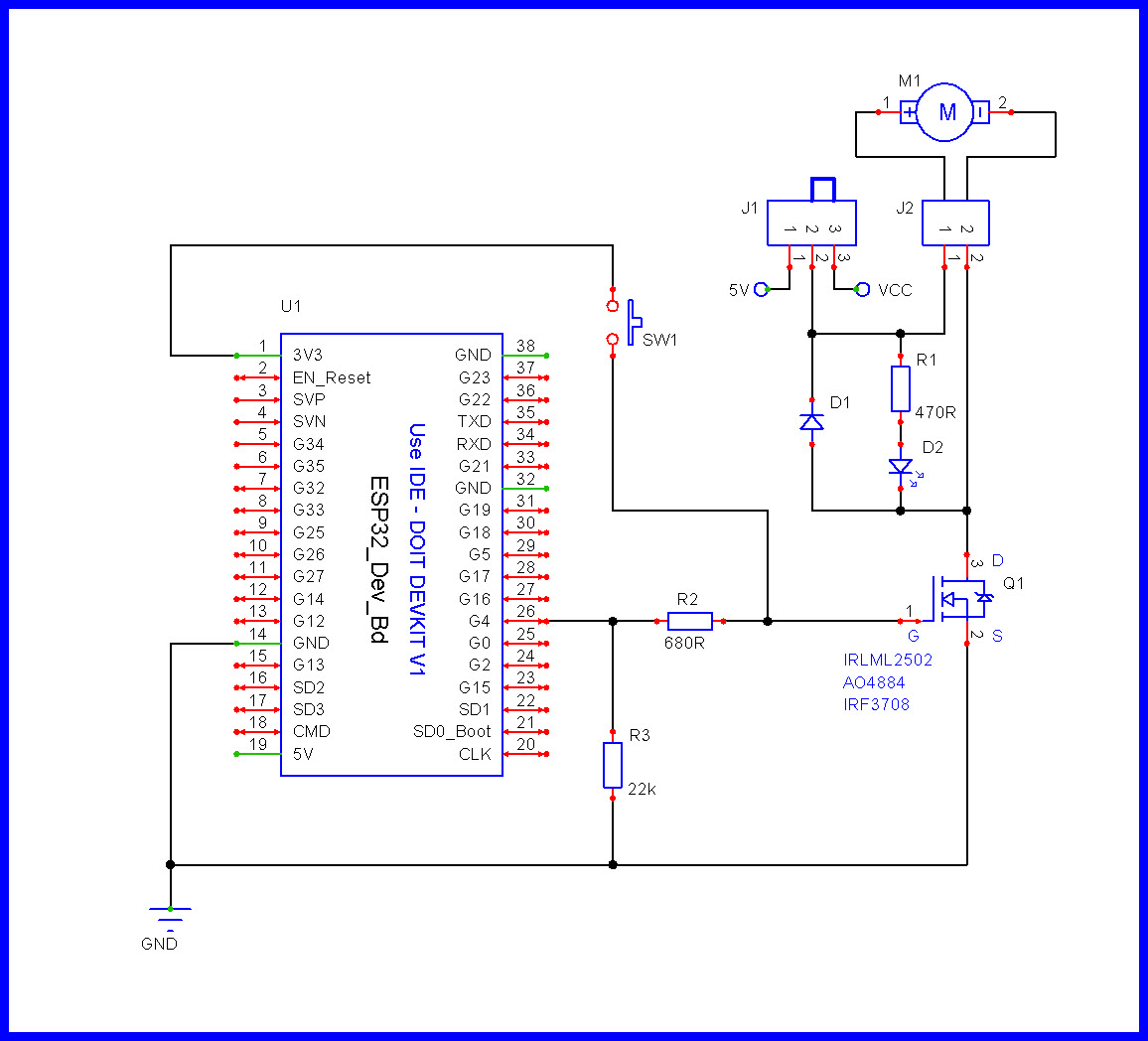
This year I would like to create a circuit board to clean up a bit of the wiring and make it compact. So I created a schematic with EasyEDA with the assistance of AI and some of my experiences.
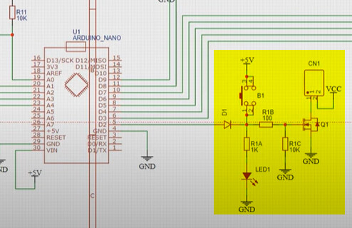
GPIO4 is directly connected to the Anode of D1, bad idea !
Sorry, I am still relatively new to this (yes, even though I have done some small circuits). How should I be connecting this? Through a resistor? What is the concern here?
There are better 3V logic level MOSFETs than the IRLZ44N.
Do you have any other specific suggestions? What makes the other MOSFETs better? I have little to no experience here so far.
The switch is wired to 5V not good since GPIO4 is also connected to the MOSFET.
Consider using a diode OR gate.
Perfect. This is what I was looking for. I will do some research to understand and select a diode OR gate (I am assuming that is one component and not a diode or a gate).
Pin current is generally measure in milli amps so that is a big fat NO. Use a mosfet or relay to control the motor and the pin controls the mosfet or relay.
Thank you for the clarification on pinheader ratings. So if I wanted to select the voltage for OUTPUT1, I should use an additional 2 MOSFETS that would be controlled based on the manual pin header selection?
I have looked over this and this appears to be great! This is much appreciated! A couple of questions to understand this properly.
It appears that the IRLML2502 is for lower amperage uses (battery powered according to Gemini). So I think that I need to use a IRLZ44N for the higher amps when working with a windshield wiper motor (potential 5amp operation, maybe 10amp starting).
Do you have a suggestion on the type of switch at J1?
Is D1 the logic OR diode?
What type of LED is at D2? It has to be compatible with 5v and 12v? Or does the resistor R1 “make” the LED bright when 12V is selected and dimmer when 5V is selected? (I have to do the math here to understand this but wanted to get the question out there.)
I never actually measured it on my prop setups but a quick Google search is showing that the steady state could be 5amp and peak starting could be 10-12amp at 12v. I don’t use anything heavy with the wiper motors.
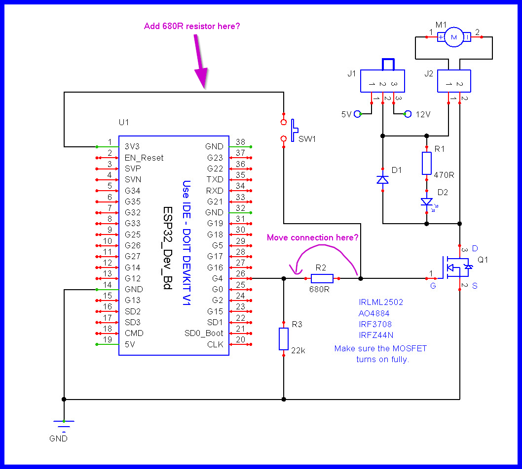
It appears that the IRLML2502 is for lower amperage uses (battery powered according to Gemini). So I think that I need to use a IRLZ44N for the higher amps when working with a windshield wiper motor (potential 5amp operation, maybe 10amp starting). You can try the IRL44N. Just make sure Vds is a low value, i.e. the MOSFET is fully turning ON.
Do you have a suggestion on the type of switch at J1? SW1 can be any switch.
Is D1 the logic OR diode? No, D1 is the motor's kickback diode. This version does not use logic OR diode.
What type of LED is at D2? It has to be compatible with 5v and 12v? Or does the resistor R1 “make” the LED bright when 12V is selected and dimmer when 5V is selected? (I have to do the math here to understand this but wanted to get the question out there.) Use a LED you have; R1 is selected for the brightness you want on the D2 LED. Let's say Vcc = 12V. Assume we need 20mA to get the desired brightness. Therefore: 12V(supply) - 2V(LED voltage) / .02A = R1 = 500R, use 470R.
Ah, now I see what this is. Also known as a flyback diode.
That all makes sense for when 12v is selected. But when 5v is selected then you have a resistor requirement of [5v(supply) - 2v (LED voltage)]/0.02A = 150R.
Or, if you use the 470R with 5v, then you will allow allow 6mA. Will that allow the LED to work?
In writing this response, it appears that I really do not understand LED’s and I need to educate myself further on this to understand it.
Regardless, I appreciate the engagement and support on this! Thank you!
I will try this. To confirm that the MOSFET is fully on, I should check the voltage on J2? If the voltage does not match the selection on J1, then is it safe to say that the resistor selection R2 needs to be changed (lowered)?