Using Hardware serial on SerialPort(2) (pins 16 and 17 of the Nano ESP32) sounds like a good idea to me, rather than using the Uno though I would go with a 3.3v ttl to usb adapter, they are always good to have around anyway.
And why not on The Tx/Rx pins which are Serial1 (Serial(1))?
I do not know if a FTDI will help with datastreamer as it only seems to like Unos.
Yes agreed, I was just keeping away from using the onboard usb as the interface.
I thought about the FTDI not being compatible but surely MS Office did not add a data streamer solely for use with a couple of Uno's, I don't know.
Thanks for adding this information. That was definitely the right thing to do. I don't have any experience with "Data Streamer" so I'm not familiar with the specifics of its UI.
That is unfortunate. I wasn't at all sure whether this would work, but thought it was worth a try at least.
This is expected.
Did you check to see if the data was received by Data Streamer after you switched the board over to that "Debug mode (Hardware CDC)" configuration? As explained by @sterretje, this configuration is achieved by selecting Tools > USB Mode > Debug mode (Hardware CDC) from the Arduino IDE menus, then uploading the sketch to the board. If you later select Tools > USB Mode > Normal mode (TinyUSB), do a double reset, then upload the sketch, it puts the board back into the "Normal mode (TinyUSB)" configuration.
Try this test:
- Close Excel (or if you can disconnect the device via the Data Streamer interface, that is also fine; the goal is to make sure Data Streamer is no longer using the serial port)
- Select the port of the UNO from Arduino IDE's Tools > Port menu.
- Open Serial Monitor.
Do you see the expected data in Serial Monitor?
Thanks again for your thoughtful response.
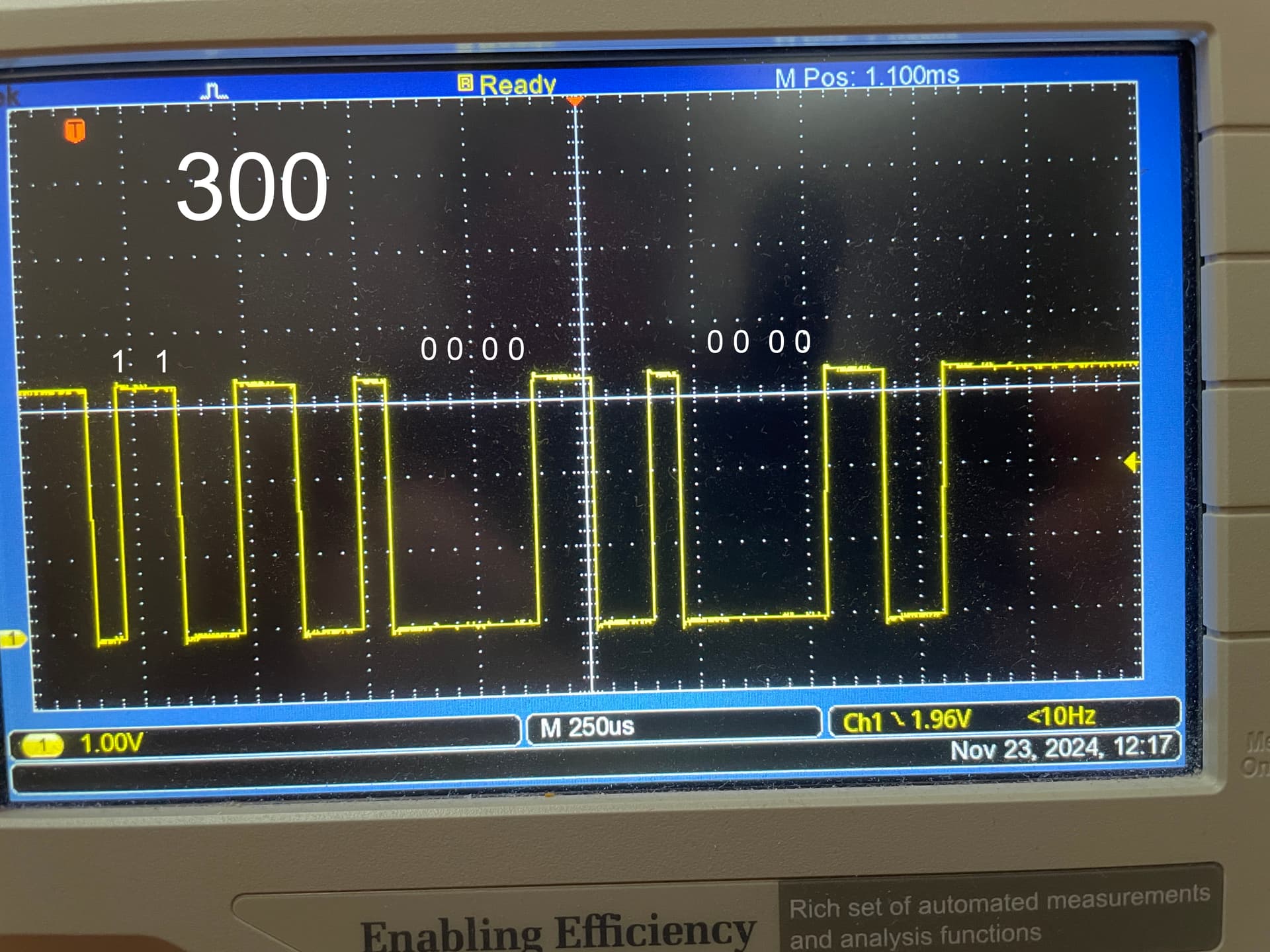
I didn't get far working through all the points, and unfortunately I won't get much more time this w/e. But I did take a series of photos which, I think, substantiate my idea that the coding is BCD, not binary. I did a series of sketches just printing one number: SerialPort.print(x), where x is
198, 199, 200, 201, 202,
298, 299, 300, 301, 302,
numbers chosen to try to show the rolls when the decimal rolls from 9 to 0.
Here are shots of the scope, with my interpretation of the binary values overwritten. The large text in the top left corner is the number being printed in each case.


Serial2 did output data in the same way. When I uploaded the sketch below, I saw '302' on my scope:
#include <HardwareSerial.h>
HardwareSerial SerialPort(2); // use UART2
int count = 302;
void setup()
{
  Serial2.begin(15200, SERIAL_8N1, 16, 17);
}
void loop()
{
  Serial2.print(count);
  delay(1000);
}
The SOC_UART_NUM I got was 3, using this sketch:
#include <HardwareSerial.h>
HardwareSerial SerialPort(2); // use UART2
int count = 302;
void setup()
{
  delay(5000);
  Serial.begin(9600);
  Serial.println(SOC_UART_NUM);
  //Serial2.begin(15200, SERIAL_8N1, 16, 17);
}
void loop()
{
  //Serial2.print(count);
  delay(1000);
}
For some reason I needed a delay in setup() or nothing was printed.
I have on old Protopic board with an FTDI FT232 chip on it. The pins are labelled differently:
Black (which means ground)
Unlabelled
Power
TX
RX
Rst
Presumably this is the same kind of board as you mention, just using some deprecated naming convention for the pins?
If it is the kind of board you had in mind, how would I use it?
Would I:
- Set the jumper to 3V3, not 5V, in order to protect my 3V3 Nano board,
- connect the Rx & Tx pins of the FTDI board to the Tx & Rx pins on the Nano (Rx connects to Tx and Tx connects to Rx),
- connect GND on the FTDI board with GND on the Nano,
3a) ignore Unlabelled, Power, Rst (leave them unconnected), - connect my laptop to the FTDI board using a USB cable,
- with Excel open, try to connect to the FTDI device?

I tried connecting the FTDI board to my laptop with a USB cable and opening Excel to see whether Excel wanted to have a chat with the FTDI device. It was not super-encouraging. Excel 'knows' there is something on port 5, but not what it is:

Given the findings in eg post #10, this is not encouraging.
@chis keep the ftdi jumper on the 3 v setting, you do not want 5 v going to the Nano.
I think it looks very encouraging but I don't have Office 365. This is the sketch MS give as an example and what you should have loaded while testing with hardware 2 serial port.
int analogSensor1;
int digitalSensor1;

void setup() {
  Serial.begin(9600);
  pinMode(2, INPUT);
}

void loop() {
  analogSensor1 = analogRead(A0);
  digitalSensor1 = digitalRead(2);

  Serial.print(analogSensor1);
  Serial.print(",");
  Serial.print(digitalSensor1);
  Serial.println();
}
If you don't have sensors attached yet use a couple of hard coded values within the loop.
Serial2.println("1,2,3");
delay(300);
It will never know as the FTDI is a generic USB device.
I had a question about the baud rate; do you need to configure that in excel / data streamer?
Apparently there is an advanced settings tab that takes you to the port configuration, other than that the default baud rate is 9600

I've had some success using a Sparkfun FT232RL USB to Serial Breakout connected to a Uno R4 WiFi.
The Uno R4 WiFi by it's self won't work with Data Streamer, as mentioned in post #11.

I connected the RX-I input to the Uno pin 1, plus the GNDs.
I used Serial1 on the Uno.
I sent the same data to Serial, and to Serial1.
int inputPin = A0;
unsigned int raw = 0;

unsigned long previousMillis = 0;
const long interval = 1000;

void setup() {
  Serial.begin(9600);
  Serial1.begin(9600);
}

void loop() {
  unsigned long currentMillis = millis();
  if (currentMillis - previousMillis >= interval) {
    previousMillis = previousMillis + interval;
    raw = analogRead(inputPin);
    Serial.println(raw);
    Serial1.println(raw);
  }
}

The Arduino Uno R4 WiFi is on COM 3.
The FTDI FT232RL is on COM 26.
Note, that the FTDI FT232RL is identified as a 'USB Serial Port', whereas the 2 x Uno R4 WiFis and a Uno R4 Minima are identified as 'USB Serial Device'.
Data Streamer will connect to COM 26, and receive data:

Here is the Serial1 data being received by Data Streamer on COM 26, and the same data from Serial displayed on the IDE's Serial Plotter.
Nice! The USB to serial adapter modules are very useful tools to have on hand.
The naming convention originates from the "FTDI cables" that were commonly used some years ago:

(note the color of the wires)
The Pro Mini board uses this labeling. It is a bit confusing because the "green" pin is labeled "GRN" on that board, which might be misinterpreted as indicating it is the ground pin.
I wouldn't get too obsessed over the labeling of the serial ports. Most likely this is only a convenience feature to help the users select the correct port. Just make sure you know which port number is your device and select that port.
Thanks everyone for the generous replies!
There seems to be a consensus that the FTDI board is likely to be a good way to go. I don't know very well how to connect up this device, and could use some help here.
Just to recap the objective: I want to receive data from an Arduino ESP32 Nano into Excel using the Data Streamer add in to Excel.
My FTDI board has 6 connections, labelled:
Black (which means ground)
Unlabelled
Power
TX
RX
Rst
Which pins should I aim for to get the data out of the ESP32? @sumguy has mentioned 16 & 17 as good candidates. Are these pin 16: D1/TX0 and pin 17: D0/RX0? (there is quite some ambiguity with pins being labelled in different ways for different purposes. I think @sumguy was referring to the physical locations on the ESP32 Nano board - but perhaps I'm wrong)
I am a bit lost about the com port opening stuff. Presumably I need
Serial[n].begin(9600);
where n is 0 or 1 or 2 - but which?
And then I need
Serial[n].println(data);
with the same n to get some data out of the pins.
Once I have a usable sketch, should I now wire up as follows:
- Set the jumper on the FTDI board to 3V3, not 5V, in order to protect my 3V3 Nano board,
- connect the black pin of the FTDI board to GND on the Nano
- ignore the unlabelled pin on the FTDI board - leave it unconnected
- ignore the power pin on the FTDI board - leave it unconnected
- connect TX on the FTDI board to D0/RX0 on the Nano
- connect Rx on the FTDI board to D1/TX0 on the Nano
- ignore the Rst pin on the FTDI board - leave it unconnected
- connect my laptop to the FTDI board using a USB cable,
- with Excel open, try to connect to the FTDI device?
Apologies for the very long question - I really do not understand how the serial communication works very well and I'm a little overwhelmed trying to make sense of all the advice from different contributors. It feels like this is close to resolution, but I need a bit more spelling stuff out in words of one syllable (not literally!) to get me over the line.
@chis I was not referring to physical distance with regard to which pins you use, if you read the Nano ESP32 cheat sheet https://docs.arduino.cc/tutorials/nano-esp32/cheat-sheet/#usb-serial--uart there are 3 hardware serial ports and 1 USB port. The cheat sheet mentions a preference for using hardware Serial1 or Serial2.
Here is an example of hardware Serial1 using pins D2 & D3
const byte RXD = 2;
const byte TXD = 3;

void setup()
{
  Serial1.begin(9600, SERIAL_8N1, RXD, TXD);  // 2,3
}
From the FTDI device you will need 3 wires TX,RX and GND
FTDI -> Black connect to Nano ESP32 GND
FTDI -> Tx connect to Nano ESP32 D2 (rx)
FTDI -> Rx connect to Nano ESP32 D3 (tx)
To test the connection with MS Office data streamer put some dummy data in a loop in the Arduino code
void loop(){
	Serial1.println("1,2,3");
	delay(300);
}
Thanks again to all who helped with this.
Here's a dropbox link to a video of the project I was working on: Dropbox
It takes a while before the 'point' of it starts to become apparent ![]()
2 Likes