Koxx
September 6, 2020, 10:08am
1
Hello,
I need to copy serial data as soon each caracter arrives.
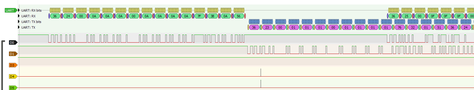
Here is my sketch... pretty simple. I've just added IO output to monitor read/write operations with a logic analyzer.
HardwareSerial hwSerCntrlToLcd(1);

#define SERIAL_CNTRL_TO_LCD_RXPIN 34
#define SERIAL_CNTRL_TO_LCD_TXPIN 13

#define PIN_READ_FLAG 33
#define PIN_WRITE_FLAG 32

#define BAUD_RATE 1200

////// Setup
void setup() {

  hwSerCntrlToLcd.begin(BAUD_RATE, SERIAL_8N1, SERIAL_CNTRL_TO_LCD_RXPIN, SERIAL_CNTRL_TO_LCD_TXPIN);

  pinMode(PIN_READ_FLAG, OUTPUT);
  pinMode(PIN_WRITE_FLAG, OUTPUT);

}

void loop() {
  readHardSerial();

}


int readHardSerial() {

  byte var;

  while (hwSerCntrlToLcd.available() > 0) {

    digitalWrite(PIN_READ_FLAG,HIGH);
    var = hwSerCntrlToLcd.read();
    digitalWrite(PIN_READ_FLAG,LOW);

    digitalWrite(PIN_WRITE_FLAG,HIGH);
    hwSerCntrlToLcd.write(var);
    digitalWrite(PIN_WRITE_FLAG,LOW);

  }

}
First issue : the available() returns only after the full data packet is recevied (see D0 line for source data, and D4 for available() starting to read data), and not when each caracter arrives. Can this be changed ?
Second issue : the write output is very delayed. The latency is so important that the visible data packed sent (D1) is the previous packet (check the second byte in the packet : 24 read / 23 write). The write() operations can be observed on D5. Why is that ?
Thanks
Hi,
Please read the post at the start of any forum , entitled "How to use this Forum".http://forum.arduino.cc/index.php/topic,148850.0.html .#7 about how to post your code.
Thanks.. Tom...
Robin2
September 6, 2020, 10:49am
4
Is this problem specific to the ESP32? In other words does a similar program work properly on an Uno?
Why are you using WHILE in this code. It seems to me that IF would be more appropriate.
while (hwSerCntrlToLcd.available() > 0)
It will make it much easier to help if you provide a full description of your project so we can understand your questions in their context.
...R
Koxx
September 6, 2020, 11:25am
5
@robin2 : thanks for your proposal.
I've just changed the "while" for a "if", no change
My projet is to receive and regenerate a full serial link with 2 UART.
It connects an electric scooter controller to his LCD.
The project will be much large (BLE, voltmeter, ampmeter, regulation...), but the start is hard.
I don't have other arduino except an ESP8266.
You forgot to flush.
    digitalWrite(PIN_WRITE_FLAG,HIGH);
    hwSerCntrlToLcd.write(var);
    hwSerCntrlToLcd.flush();
    digitalWrite(PIN_WRITE_FLAG,LOW);
By the way, why does this function pretend to return an int, when it doesn't?
int readHardSerial() {
Koxx
September 6, 2020, 11:59am
8
flush has a really weird effect.
I read and understood it should only affect the TX (force send), but clearly, it doesn't more than that. The RX seems affected too.
https://koxx3.fr.eu.org:8086/smartlcd/Capture4.PNG
for the 'int' return, I had a counter inside before simplifying the sketch
Koxx:
I read and understood it should only affect the TX (force send), but clearly, it doesn't more than that. The RX seems affected too.
What do you mean, flush has a weird effect? This is the first time I've heard that. It doesn't need to affect more than TX, that is what it is designed for.
Your problem is caused by characters being held in the TX buffer. There is nothing wrong with your RX buffer, or with the 'available()' function.
It's not clear from your post whether you tried my suggestion.
Koxx
September 6, 2020, 12:05pm
10
sorry, wrong forum tag.
Here is the result with flush() as you suggested.
Please post your entire revised sketch.
Also, it's possible that this is related to your using the same Serial port for TX and RX. Although, I can't think of any specific reason. Is there another port on the ESP32 that you can use?
Koxx
September 6, 2020, 12:10pm
12
Here it is !
Thanks again for your help. I am strungling with this since 48h...
HardwareSerial hwSerCntrlToLcd(1);

#define SERIAL_CNTRL_TO_LCD_RXPIN 34
#define SERIAL_CNTRL_TO_LCD_TXPIN 13

#define PIN_READ_FLAG 33
#define PIN_WRITE_FLAG 32

#define BAUD_RATE 1200

////// Setup
void setup() {

  hwSerCntrlToLcd.begin(BAUD_RATE, SERIAL_8N1, SERIAL_CNTRL_TO_LCD_RXPIN, SERIAL_CNTRL_TO_LCD_TXPIN);

  pinMode(PIN_READ_FLAG, OUTPUT);
  pinMode(PIN_WRITE_FLAG, OUTPUT);

}

void loop() {
  readHardSerial();

}


void readHardSerial() {

  byte var;

  if (hwSerCntrlToLcd.available() > 0) {

    digitalWrite(PIN_READ_FLAG,HIGH);
    var = hwSerCntrlToLcd.read();
    digitalWrite(PIN_READ_FLAG,LOW);

    digitalWrite(PIN_WRITE_FLAG,HIGH);
    hwSerCntrlToLcd.write(var);
    hwSerCntrlToLcd.flush();
    digitalWrite(PIN_WRITE_FLAG,LOW);

  }

}
The ESP32 has 2 pin matrix ports Port 0 or A and Port 1 or B.
#define SERIAL_CNTRL_TO_LCD_RXPIN 34

#define PIN_READ_FLAG 33
#define PIN_WRITE_FLAG 32
For starters.
It becomes reasonable that serial issues could develop with the use of PORT B as serial inputs. Port A and Port B have different characteristics. Might be a good idea to understand the differences. see ESP32 API API Reference - ESP32 - — ESP-IDF Programming Guide latest documentation .
Koxx
September 6, 2020, 12:24pm
14
Idahowalker:
#define SERIAL_CNTRL_TO_LCD_RXPIN 34
#define PIN_READ_FLAG 33#define PIN_WRITE_FLAG 32
For starters.

It becomes reasonable that serial issues could develop with the use of PORT B as serial inputs. Port A and Port B have different characteristics. Might be a good idea to understand the differences. see ESP32 API https://docs.espressif.com/projects/esp-idf/en/latest/esp32/api-reference/index.html.
thanks, but I didn't see any warning about changing the pin to this location in Espressif documentation (nor different behavior).
Koxx
September 6, 2020, 2:45pm
16
WHOOOO !
I found this thread :
opened 11:09AM - 31 Aug 17 UTC
closed 06:35PM - 22 Oct 19 UTC
Status: Stale
### Hardware:
Board: Own design based on ESP-WROOM-32
Core Installation/… update date: 25/aug/2017
IDE name: Arduino IDE
SDK version: v3.0-dev-270-g69646f6d
Flash Frequency: 80Mhz
Upload Speed: 512000
### Description:
I'm working on a serial protocol with ACK that I used with esp8266 without troubles
The trouble is that esp32 serial ports with HardwareSerial are too slow for me.
In my design the esp32 works as master in a multimaster environment similar to RS485, I send a command to a slave and the slave send me an ACK, I wait for the response command from salve and I must send an ACK to slave in a window time of 500uS after the slave response, but in the measures I made with my entire system running I'm not able to send the ACK in less than 4 o 5 mS.
In the sketch I send, I'm working at 19200 bauds, I used a serial sniffer to assess the time. Before : is the elapsed time in milliseconds, in the first line is the command sent by the master and the slave ACK, in the second line is the response of the slave, and in the third line the master ACK and a new response from the slave.
The transmission of the 7 bytes last 3.6mS and the ACK is sent in 2.4mS, this is one of the better times I got because there isn't running the BLE or the Wifi stack
P300254927:021D58C292421A
P300254938:03C059C202CD5D
P300254944:CA03C059C202CD5D
Another issue, if I use the serial2.flush command the ESP32 send rubbish to the bus, no matter before or after the write command
### Sketch:
#include "HardwareSerial.h"
unsigned long maxTimeout = 20; //20 mS timeOut
int speed;
HardwareSerial Serial2(2);
void setTimeOut(unsigned long n){
maxTimeout = n;
}
unsigned long getTimeOut(void){
return maxTimeout;
}
int serial_read(uint8_t *dataStream, int size){
int count = 0;
unsigned long timeOut = getTimeOut() + millis(); //Actual time
while((millis() < timeOut) && (count < size)){// Wait until data recived and no timeout
if(Serial2.available()){
dataStream[count]=Serial2.read();
count++;
}
yield();
}
return count;
}
void setSerial(int bus_speed, byte parity){ //TODO velocity changes hangs on
speed = bus_speed;
//Serial2.flush(); //wait to the send buffer
delay(2); //wait for the last char
if(parity){
Serial2.begin(bus_speed, SERIAL_8E1);
}else{
Serial2.begin(bus_speed, SERIAL_8N1);
}
yield();
}
int serial_read_validator(uint8_t *dataStream, int size, uint8_t *validator){
int count = 0;
unsigned long timeOut = getTimeOut() + millis(); //Actual time
while((millis() < timeOut) && (count < size)){// Wait until data recived and no timeout 200mS
if(Serial2.available()){
dataStream[count]=Serial2.read();
if(count<4){
if(dataStream[count] == validator[count]){
count++;
}else{
count = 0;
}
}else{
count++;
}
}
yield();
}
return count;
}
void setup() {
Serial2.begin(19200, SERIAL_8N1);
}
void loop() {
uint8_t comm1[]={0x02, 0x1D, 0x58, 0xC2, 0x92, 0x42};
uint8_t val[]={0x02, 0x1D, 0x58, 0xC2};
uint8_t resp[128];
uint8_t ack[]={0xCA};
int readed;
Serial2.write(comm1, 6);
//Serial2.flush();
readed = serial_read_validator(resp, 7, val);
if((readed == 7) && (resp[6]==0x1A)){
serial_read(resp, 7);
Serial2.write(ack, 1);
}
delay(100);
}
And I patched this file with the recommandations :
uart_t* uartBegin(uint8_t uart_nr, uint32_t baudrate, uint32_t config, int8_t rxPin, int8_t txPin, uint16_t queueLen, bool inverted)
{
    if(uart_nr > 2) {
        return NULL;
    }

    if(rxPin == -1 && txPin == -1) {
        return NULL;
    }

    uart_t* uart = &_uart_bus_array[uart_nr];

#if !CONFIG_DISABLE_HAL_LOCKS
    if(uart->lock == NULL) {
        uart->lock = xSemaphoreCreateMutex();
        if(uart->lock == NULL) {
            return NULL;
        }
    }
#endif

    if(queueLen && uart->queue == NULL) {
        uart->queue = xQueueCreate(queueLen, sizeof(uint8_t)); //initialize the queue
        if(uart->queue == NULL) {
            return NULL;
        }
    }
    if(uart_nr == 1){
        DPORT_SET_PERI_REG_MASK(DPORT_PERIP_CLK_EN_REG, DPORT_UART1_CLK_EN);
        DPORT_CLEAR_PERI_REG_MASK(DPORT_PERIP_RST_EN_REG, DPORT_UART1_RST);
    } else if(uart_nr == 2){
        DPORT_SET_PERI_REG_MASK(DPORT_PERIP_CLK_EN_REG, DPORT_UART2_CLK_EN);
        DPORT_CLEAR_PERI_REG_MASK(DPORT_PERIP_RST_EN_REG, DPORT_UART2_RST);
    } else {
        DPORT_SET_PERI_REG_MASK(DPORT_PERIP_CLK_EN_REG, DPORT_UART_CLK_EN);
        DPORT_CLEAR_PERI_REG_MASK(DPORT_PERIP_RST_EN_REG, DPORT_UART_RST);
    }
    uartFlush(uart);
    uartSetBaudRate(uart, baudrate);
    UART_MUTEX_LOCK();
    uart->dev->conf0.val = config;
    #define TWO_STOP_BITS_CONF 0x3
    #define ONE_STOP_BITS_CONF 0x1

    if ( uart->dev->conf0.stop_bit_num == TWO_STOP_BITS_CONF) {
        uart->dev->conf0.stop_bit_num = ONE_STOP_BITS_CONF;
        uart->dev->rs485_conf.dl1_en = 1;
    }
    UART_MUTEX_UNLOCK();

    if(rxPin != -1) {
        uartAttachRx(uart, rxPin, inverted);
    }

    if(txPin != -1) {
        uartAttachTx(uart, txPin, inverted);
    }

//////////////////////////////////////////////////////////////////////
//////////////////////////////////////////////////////////////////////
//////////////////////////////////////////////////////////////////////
uart->dev->idle_conf.rx_idle_thrhd = 0;
uart->dev->idle_conf.tx_idle_num = 0;
uart->dev->idle_conf.tx_brk_num = 0;
uart->dev->conf1.rxfifo_full_thrhd = 1;
uart->dev->conf1.rx_tout_thrhd = 1;
//////////////////////////////////////////////////////////////////////
//////////////////////////////////////////////////////////////////////
//////////////////////////////////////////////////////////////////////

    addApbChangeCallback(uart, uart_on_apb_change);
    return uart;
}
Now, this is simply PERFECT !
I use another SoftwareSerial for the LCD_TO_CNTRL.
I have setup serial on the ESP32 in the following fashion, under the freeRTOS OS.
#include <HardwareSerial.h>
HardwareSerial GPSSerial ( 1 );
// pin 2=RX, pin 15=TX
HardwareSerial LIDARSerial ( 2 );
// pin 26=RX, pin 25=TX

void setup()
{
  //
  LIDARSerial.begin ( SerialDataBits, SERIAL_8N1, 26, 25 );
  GPSSerial.begin ( GPS_DataBits, SERIAL_8N1, 2, 15 ); // begin GPS hardware serial
}
//
void loop() {} // runs on core 1
/// this is the serial receiver
void fReceiveSerial_LIDAR( void * parameters  )
{
  bool BeginSentence = false;
  char OneChar;
  char *str;
  str = (char *)ps_calloc(300, sizeof(char) ); // put str buffer into PSRAM
  // log_i("Free PSRAM before String: %d", ESP.getFreePsram());
  for ( ;; )
  {
    EventBits_t xbit = xEventGroupWaitBits (eg, evtReceiveSerial_LIDAR, pdTRUE, pdTRUE, portMAX_DELAY);
    if ( LIDARSerial.available() >= 1 )
    {
      while ( LIDARSerial.available() )
      {
        OneChar = LIDARSerial.read();
        if ( BeginSentence )
        {
          if ( OneChar == '>')
          {
            if ( xSemaphoreTake( sema_ParseLIDAR_ReceivedSerial, xSemaphoreTicksToWait10 ) == pdTRUE )
            {
               xQueueOverwrite( xQ_LIDAR_Display_INFO, ( void * ) &str );
              xEventGroupSetBits( eg, evtParseLIDAR_ReceivedSerial );
              //
            }
            BeginSentence = false;
            break;
          }
          strncat( str, &OneChar, 1 );
        }
        else
        {
          if ( OneChar == '<' )
          {
            strcpy( str, ""); // clear string buffer
            BeginSentence = true; // found beginning of sentence
          }
        }
      } //  while ( LIDARSerial.available() )
    } //if ( LIDARSerial.available() >= 1 )
    xSemaphoreGive( sema_ReceiveSerial_LIDAR );
    //        log_i( "fReceiveSerial_LIDAR " );
    //        log_i(uxTaskGetStackHighWaterMark( NULL ));
  }
  free(str);
  vTaskDelete( NULL );
} //void fParseSerial( void * parameters  )
Note the use of if ( LIDARSerial.available() >= 1 ) and not if ( LIDARSerial.available() > 0 ). I found that with the DUE, STM32 and the ESP32 if ( LIDARSerial.available() >= 0 ) does not work as well as if ( LIDARSerial.available() >= 1 ).