Hi everyone, i recently bought an EPS32 (KEYESTUDIO ESP32 WROVER) board for a project.
Setup everything loaded some script to test some components but when i decideed to use the servos i found out that the Base arduino Library (Servo.h) doesent work, looked up for solutions and found out about ESP32Servo.h (v3.0.8), installed but i cant get to run any of my servos, they work fine on my other arduino borads.
The Servos are DS04-NFC (continuous) and SG90 (180°) i cant manage to make em move, i initially thought that the voltage in the middle pins was at 3.3v and not at 5v but after checking it, it is 5v, i saw a lot of video online but while doing the same i can get it to work.
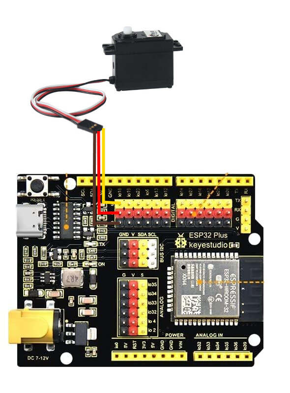
If someone can help, here a basic schema on how i attached the servo:
in the code i tried every combination while setting up the frequency to 50, allocating the ESP32PWM, attaching the servo using only the pin or specifing 1000 as min, 2000 as max, using write(180) or write(0) and even writeMicroseconds(2000),writeMicroseconds(1500) and writeMicroseconds(1000) , all this for the continuous one then i jumped on the other one and used the basic for with delays. i cant get it to work, if someone can tell me what i am doing wrong.
Your fuzzy picture does not show how it is connected. Please post a simple annotated schematic showing all connections, power, ground, and power sources.
What do you mean, the image is clear the only thing i didn't mention is that i am using USB as power source but i assumed it obvious that's on me and the pin 18 but i think wont make much a difference, anyway i solved it, thanks.
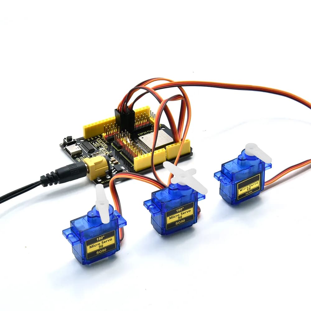
In general, most of the boards doesn't come with a voltage regulator that can handle many Ampéres of current. So it's recommended to have a separate power supply for servos and motors in general. In the other hand, some custom boards are made exactly for this use, which seems to be your case, given that the very Keyestudio site uses this image as an example:
When you power a motor from an Arduino/ESP board, both the 5v and GND current paths run thru traces on the Arduino PCB.
These currents are high in level and have motor noise mixed in.
An external 5-7v external supply (with a common GND connection to the ARDUINO) connects to the servo directly bypassing the Arduino PCB (and subsequent traces).
We refer to this as a star connection (you may want to add an On/Off switch).
This prevents trace to trace noise coupling.
Never power inductive loads from your Arduino 5V pin.
This pin can only be used with non inductive lower current loads.
Can be found here.
Servo power comes from the USB-C connector, through a backflow protection fet.
Powering servos from a computer port is a bad idea.
Make sure you have a spare computer. Or use a tablet supply instead.
Three small SG-90 servos plus an ESP32 could draw peak currents of 2.5Amp.
Leo..