Good Morning Everyone,
Project Objective:
Bare with me as this is my first post here, but I've been stumped on a problem with my code for a few days now and have resorted to finding help online. The overall objective of this project is to have a (TX) transmit incoming data from the NEO-6M GPS Module over to the (RX) using the SX1276 LoRa Module to allow the user to view the readings on an SSD1306 OLED Display. The description of component usage for the TX and RX are listed below:
(TX):
- ESP32 Dev Module
- SX1276 LoRa Module
- NEO-6M GPS Module
- SSD1306 OLED Display (Optional/ Just to See the Readings for Now)
(RX):
- ESP32 Dev Module
- SX1276 LoRa Module
- SSD1306 OLED Display
Project Issue
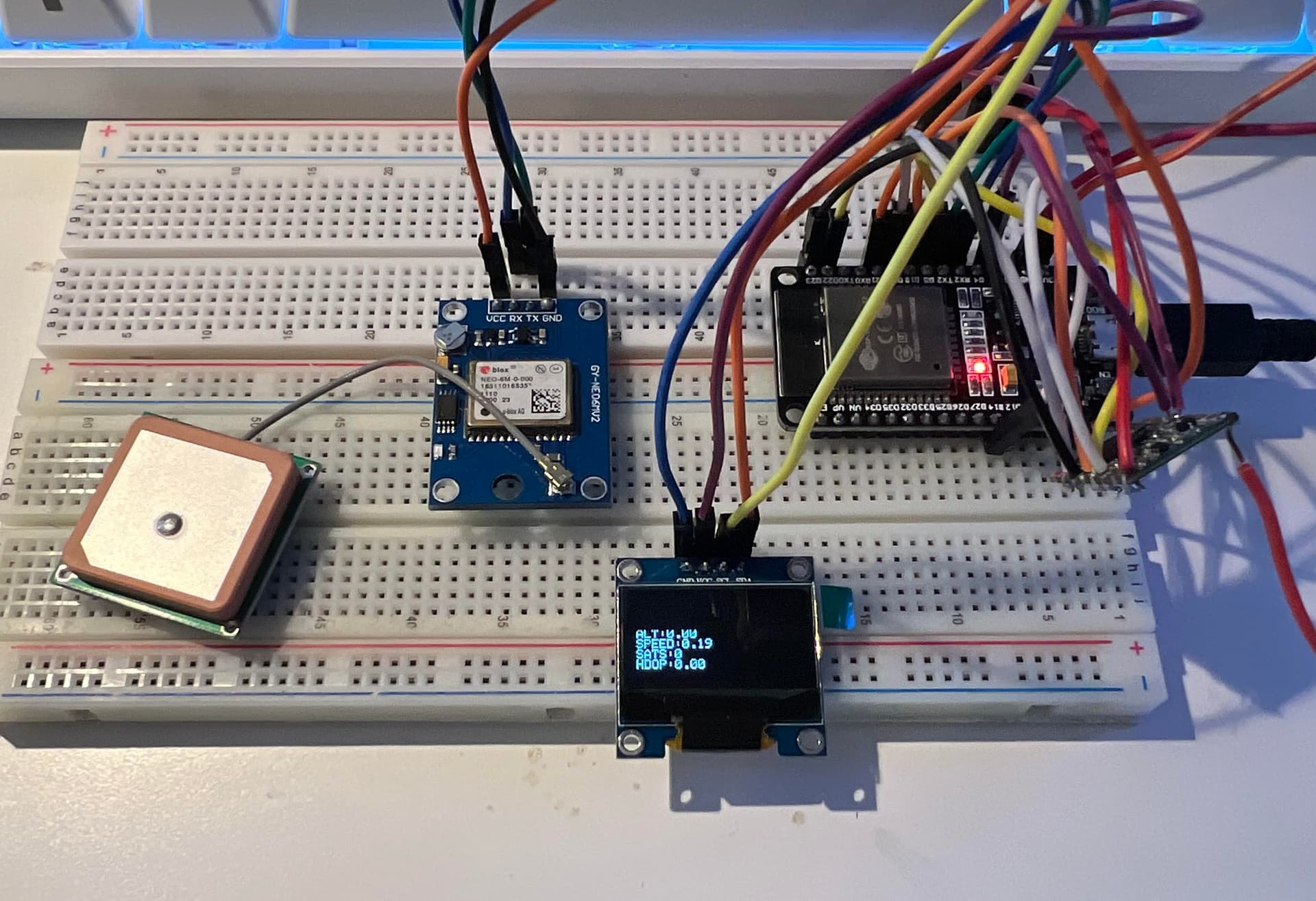
When the code (listed below) is uploaded to the board, everything works out perfectly. The (TX) is receiving incoming data from the NEO-6M GPS and the SSD1306 OLED Display is giving off the proper readings for the viewer to see. However; if you notice, the LoRa portion of the code that's listed near the bottom of the code is grayed out for a reason. Every time I activate this portion of code into the overall code and upload it to the board, I get a few problems. The altitude, number of satellites, and HDOP readings all get bumped down to zero as if they're not receiving any data. However the latitude, longitude, and speed are all reading correctly. I want to ensure that the incoming data will be retrieved correctly before sending it over to the (RX). If anyone has any helpful tips to fix this issue, that'd be great. Thank you for your time today and have a great day!
//Libraries for LoRa
#include <SPI.h>
#include <LoRa.h>

//Libraries for Adafruit SSD1306 OLED Display
#include <Wire.h>
#include <Adafruit_GFX.h>
#include <Adafruit_SSD1306.h>

//Libraries for GPS
#include <TinyGPSPlus.h>
#include <SoftwareSerial.h>

//Define the Pins Used by the LoRa Transceiver Module
#define SCK 18
#define MISO 19
#define MOSI 23
#define SS 5
#define RST 14
#define DIO0 2

//Define Radio Frequency Used in North America
#define BAND 915E6

//OLED Pins
#define OLED_SDA 21
#define OLED_SCL 22

//Define Adafruit SSD1306 OLED Display Size
#define SCREEN_WIDTH 128 // OLED display width, in pixels
#define SCREEN_HEIGHT 64 // OLED display height, in pixels

//Define RX and TX Pinout on NEO6M GPS Module
static const int RXPin = 17;
static const int TXPin = 16;

static const uint32_t GPSBaud = 9600;

//Establish NEO6M GPS Module
TinyGPSPlus gps;
SoftwareSerial gpsSerial(RXPin, TXPin);

//Establish Adafruit SSD1306 OLED Display
Adafruit_SSD1306 display(SCREEN_WIDTH, SCREEN_HEIGHT, &Wire, -1);

//Setup
void setup() {
  //Initialize Serial Monitor
  Serial.begin(115200);
  //Initialize GPS Serial Monitor
  gpsSerial.begin(GPSBaud);
  //Change Sync Word (0xF3) to Match the Receiver/The Sync Word assures you don't get LoRa Messages from Other LoRa Transceivers/Ranges from 0-0xFF
  LoRa.setSyncWord(0xF3);
  //SPI LoRa Pins
  SPI.begin(SCK, MISO, MOSI, SS);
  //Setup LoRa Transceiver Module
  LoRa.setPins(SS, RST, DIO0);
  //Activates Serial Connection w/ Hardware
  while (!Serial);

  //Reset OLED Display via Software
  pinMode(-1, OUTPUT);
  digitalWrite(-1, LOW);
  delay(20);
  digitalWrite(-1, HIGH);

  //Initialize OLED
  Wire.begin(OLED_SDA, OLED_SCL);
  if(!display.begin(SSD1306_SWITCHCAPVCC, 0x3C, false, false)) { // Address 0x3c for 128x32
    Serial.println(F("SSD1306 allocation failed"));
    for(;;); // Don't Proceed, Loop Forever
  }

  //Display "LoRa Transmitter" for Booting Process
  display.clearDisplay();
  display.setTextColor(WHITE);
  display.setTextSize(1);
  display.setCursor(0,0);
  display.print("LoRa Transmitter");
  display.display();

  //If "LoRa Connection Failed" Display "LoRa Connection Failed"
  if (!LoRa.begin(BAND)) {
    Serial.println("LoRa Connection Failed");
    while (1);
  }
  //If "LoRa Connection Succeeded" Display "LoRa Connection Succeeded"
  Serial.println("LoRa Initializing OK!");
  display.setCursor(0,10);
  display.print("LoRa Initializing OK!");
  display.display();
  display.clearDisplay();
  delay(2000);
}

//Loop
void loop() {
  while (gpsSerial.available() > 0){
    gps.encode(gpsSerial.read());
    if (gps.location.isUpdated()){
      //Display Readings into Serial Monitor
      //Latitude
      Serial.print("Latitude: ");
      Serial.print(gps.location.lat(), 6);
      //Longitude
      Serial.print(" Longitude: ");
      Serial.print(gps.location.lng(), 6);
      //Altitude
      Serial.print(" Altitude: ");
      Serial.print(gps.altitude.meters(), 2);
      //Speed
      Serial.print(" Speed: ");
      Serial.print(gps.speed.mps(), 2);
      //Satellites
      Serial.print(" Satellites: ");
      Serial.print(gps.satellites.value());
      //HDOP
      Serial.print(" HDOP: ");
      Serial.print(gps.hdop.hdop(), 2);
      //Serial.print(" Date: ");
      //Serial.print(gps.date.month());
      //Serial.print("/");
      //Serial.print(gps.date.day());
      //Serial.print("/");
      //Serial.print(gps.date.year());
      //Intiate Next Line for Information
      Serial.println();

      //Display Readings into SSD1306 OLED Display
      display.setCursor(0,10);
      display.print("LAT:");
      display.println(gps.location.lat(), 6);
      display.print("LONG:");
      display.println(gps.location.lng(), 6);
      display.print("ALT:");
      display.println(gps.altitude.meters(), 2);
      display.print("SPEED:");
      display.println(gps.speed.mps(), 2);
      display.print("SATS:");
      display.println(gps.satellites.value());
      display.print("HDOP:");
      display.println(gps.hdop.hdop(), 2);
      //display.print("DATE:");  //Optional
      //display.println(gps.date.month());  //Optional
      //display.println("/");  //Optional
      //display.println(gps.date.day());  //Optional
      //display.println("/");  //Optional
      //display.println(gps.date.year());  //Optional
      display.display();
      display.clearDisplay();

      //LoRa.beginPacket();
      //LoRa.print("LAT:");
      //LoRa.println(gps.location.lat(), 6);
      //LoRa.print("LONG:");
      //LoRa.println(gps.location.lng(), 6);
      //LoRa.print("ALT:");
      //LoRa.println(gps.altitude.meters(), 2);
      //LoRa.print("SPEED:");
      //LoRa.println(gps.speed.mps(), 2);
      //LoRa.print("SATS:");
      //LoRa.println(gps.satellites.value());
      //LoRa.print("HDOP:");
      //LoRa.println(gps.hdop.hdop(), 2);
      //LoRa.endPacket();

      //delay(5000);
    }
  }
}
Here are pictures of the before and after from uploading the code. The latitude and longitude readings are blacked out for obvious reasons.
Before (Code w/ the LoRa Part Grayed Out):

After (Code w/ LoRa Part):