david_prentice:
Think about it.
The Arduino system means that everyone has the "core" set of libraries and examples that come with the IDE.
Everyone can access any "approved" third party libraries via the IDE Library Manager.
So you can paste a sketch or attach a project ZIP to the Forum.
And anyone in the world can replicate your project.
Yes, you can flout the C / C++ conventions if you want. e.g. code in H files
But you will keep people happier if you just create a minimal example that exhibits your problem.
Or at least add any "unusual files" to local tabs in your project.
Build your project yourself first. All the libraries, versions and locations are reported in a "verbose compile".
You just need to go through the list in the Library Manager.
David.
p.s. we make allowances for young members, newcomers, non-English speakers, ...
I am guessing that you don't fall into those categories.
I understand, i made a new really small project with just the files needed to compile. I do get the same error again so i think if you can compile with the same hardware you should get it too.
I am a non-english speaker but i understand i should have done more to get help from others.
I really hope the new zip file has enough information to compile it (i included all the libraries).
bodmer:
ESP32 IO35 is input only. Are you expecting it to be an output? Fix that if you expect to reset the RC552. Note: IO34, 36 and 39 are also input only.
Other potential mistakes:
-
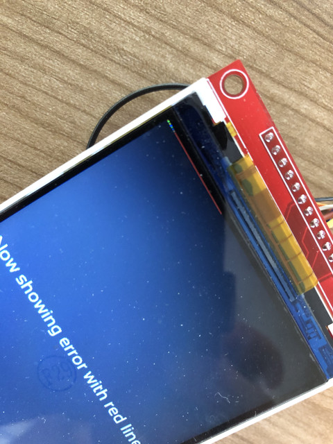
If your are using tft.startWrite() in your code make sure you use tft.endWrite() before you access any other SPI devices. The red stripes are likely to be cause by messages that are destined for the RF522 are also going to the TFT.
-
Check you really have wired it up as you think you have. Look at the chip select pins again and again and again.
-
Run the Read_User_Setup diagnostic sketch to make sure you have configured the TFT_eSPI library correctly.
I expect the software lines you posted are not the problem, they just happen to create conditions for a fault in a completley different part of the code or hardware configuration setup to show itself. That is why full information disclosure is important!
Thanks for stepping in.
I switched from IO35 to IO33 for the reset but the result is still the same.
I didn't use tft.startWrite() so far but if this can solve my problem i can see if i can modify the code to this
I have checked multiple times and i really think my wires are as i displayed on the image. The only thing i cannot get used to is the gpio port numbering. I have used arduino's before (this is my first time using an ESP32) but on the arduino GPIO 6 is pin 6.
Here i feel the numbers can be different.
If i run the Read_User_Setup i get this output and i am not sure if this is what i should get:
09:16:50.329 -> ets Jun  8 2016 00:22:57
09:16:50.329 ->
09:16:50.329 -> rst:0x10 (RTCWDT_RTC_RESET),boot:0x33 (SPI_FAST_FLASH_BOOT)
09:16:50.329 -> configsip: 0, SPIWP:0xee
09:16:50.329 -> clk_drv:0x00,q_drv:0x00,d_drv:0x00,cs0_drv:0x00,hd_drv:0x00,wp_drv:0x00
09:16:50.329 -> mode:DIO, clock div:1
09:16:50.329 -> load:0x3fff0018,len:4
09:16:50.329 -> load:0x3fff001c,len:1216
09:16:50.329 -> ho 0 tail 12 room 4
09:16:50.329 -> load:0x40078000,len:9720
09:16:50.329 -> ho 0 tail 12 room 4
09:16:50.329 -> load:0x40080400,len:6352
09:16:50.329 -> entry 0x400806b8
09:16:51.395 ->
09:16:51.395 -> [code]
09:16:51.395 -> TFT_eSPI ver = 2.2.6
09:16:51.395 -> Processor    = ESP32
09:16:51.395 -> Frequency    = 240MHz
09:16:51.395 -> Transactions = Yes
09:16:51.395 -> Interface    = SPI
09:16:51.395 -> Display driver = 7796
09:16:51.395 -> Display width  = 320
09:16:51.395 -> Display height = 480
09:16:51.395 -> MOSI    = GPIO 23
09:16:51.395 -> MISO    = GPIO 19
09:16:51.395 -> SCK     = GPIO 18
09:16:51.395 -> TFT_CS   = GPIO 15
09:16:51.395 -> TFT_DC   = GPIO 2
09:16:51.395 -> TFT_RST  = GPIO 4
09:16:51.395 -> Font GLCD   loaded
09:16:51.395 -> Font 2      loaded
09:16:51.395 -> Font 4      loaded
09:16:51.395 -> Font 6      loaded
09:16:51.395 -> Font 7      loaded
09:16:51.395 -> Font 8      loaded
09:16:51.395 -> Smooth font enabled
09:16:51.395 ->
09:16:51.395 -> Display SPI frequency = 27.00
09:16:51.395 ->
My file is 4MB in size so i can't upload it here. I have uploaded it without the libraries (i have used the MFRC522 library AND TFT_eSPI) but i also uploaded everything here:
WeTransfer - Send Large Files & Share Photos Online - Up to 2GB Free (wetransfer link)
Thanks again, i really appreciate all the help and please let me know if i didn't do anything correct with posting the files
sourcecode.zip (93.2 KB)