I’m very new to the Arduino/ESP32 space and was hoping to get some help. I’ve been working on a simple project using an ESP32 board and an L298 motor controller to drive a 12V DC motor.
I’ve confirmed that all of my hardware components should be functioning properly, so I suspect the issue may be related to my code or possibly a wiring mistake. Any help would be greatly appreciated—I’ve been stuck on this for weeks.
Here’s the code I’m currently using:
// Motor control pins
#define ENA 14
#define IN1 27
#define IN2 26

void setup() {

// Pin setups
  pinMode(ENA, OUTPUT);
  pinMode(IN1, OUTPUT);
  pinMode(IN2, OUTPUT);

  Serial.println("Motors now waiting...");
}

void loop() {
Serial.begin(115200);
digitalWrite(ENA, 25);
digitalWrite(IN1, HIGH); // control motor direction
digitalWrite(IN2, LOW); // control motor direction

delay(10);

}
The L298 motor controller is an obsolete part, it gets hot as it drops about 1.5Volts per lead so a 12V supply will give you about 9 Volts on the motor.
Your description is misleading, your batteries will be about 3.7 for normal operation and in series that gives you 7.4 volts, a lot less then thee implied 12V. Now subtract 3V for the L298 leaving 4.4 volts
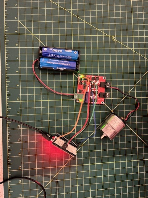
I cannot tell from your not to clear picture how you have wired this. It would be a big help if you posted an annotated schematic showing exactly how it is wired and also show the power sources and links to each of the hardware devices.
The module that is shown on the pic is not a L298, although some dealer sites like Aliexpress call it like this. Google Lens pointed me out to the XY160D, a DRV-1011 mosfet based board.
should be analogWrite(255) or digitalWrite(1) but digitalWrite(25) does the same thing
i've never seen a motor board like that, with external mosfets. Can you list the labels on the header. Presumably there should be a IN0, IN1 and EN pins for 2 motors
Thanks everyone for the help and the suggestions. I made the recommended change to the analogWrite part, and I also tried switching from the ESP32 to an Arduino Uno R4 using the same code. With the Uno, it worked perfectly, which makes me think the issue was with my wiring on the ESP32 side, maybe something with the 5V pins.
// Motor control pins
int ENA = 9;
int IN1 = 8;
int IN2 = 7;
int ENAB = 11;
int IN3 = 13;
int IN4 = 12;

void setup() {

// Pin setups
  pinMode(ENA, OUTPUT);
  pinMode(ENAB, OUTPUT);
  pinMode(IN1, OUTPUT);
  pinMode(IN2, OUTPUT);
  pinMode(IN3, OUTPUT);
  pinMode(IN4, OUTPUT);

  Serial.println("Motors now waiting...");
}

void loop() {
Serial.println("Motors now running...");
digitalWrite(IN1, HIGH); // control motor direction
digitalWrite(IN2, LOW); // control motor direction
digitalWrite(IN3, LOW); // control motor direction
digitalWrite(IN4, HIGH); // control motor direction
analogWrite(ENA, 100);
analogWrite(ENAB, 100);
delay(10);

}
My goal is to control this project with a PS4 controller instead of hard-coding the motor movement, so I’d like to understand why the ESP32 setup didn’t work. Any guidance is appreciated.
For reference, here’s how I had the ESP32 connected to the motor driver: