ESP32 to ESP32 communications options

I'm working on a greenhouse monitor/control system. Currently I have a battery powered ESP32 with a BME280 sensor working. The ESP32 connects to my home WiFi router and I send the BME values to ThinkSpeak for remote monitoring. I also use the WiFi to sync to NTP time for a clock. I will have a hydroponic system in the greenhouse so I will add some other sensors and pump control.

The next step is to have a control unit in the house. My plan is to use another ESP32 with a TFT touch screen. From here I want to display the values from the remote as well as control the pumps, set limits and time on values for the remote sensors and pumps. Getting the sensors, pumps and TFT working should be no big deal, I've had that all working with Arduino's and the ESP32 isn't that much different for those kinds of things. The remote unit is about 60 feet from the room of my house, a straight shot, where I will have the control unit.

So before I go to far down the wrong road, I've been there, my questions and what I'm asking for is suggestions on the communications between the ESP's and keeping the WiFi connection on the remote. I see that I could use ESP-Now for the ESP to ESP connection but I've see conflicting info as far as if I can still have the WiFi to the router or not with ESP-Now, Can I?

I'm not familiar with what I can do with Bluetooth other than a couple of YouTube videos that show I could use that for some control. Can that be used in some way?

Are there other options as to get all of this working?

Thanks for all suggestions and comments
John

Why not let one ESP do the lot?

You already know that Wifi works, as I understand. What's the disadvantage using Wifi for the second controller?

@Railroader, I need 2 ESP's one in the greenhouse and one in my house. I didn't say there was a disadvantage, I guess that's what I'm asking what are the advantages/disadvantages of the different methods. I would think that would be a good option. I'll assume, I haven't done that yet as I'm just getting into the ESP world, that I could also connect the house unit to my router and set up duplex communications to the greenhouse ESP.

Thanks for the suggestion, I'll look into that

Something like this?

@johnerrington That looks good, I'm surprised I missed that as I've been looking at a lot of his tutorials.

Looks like I have some homework to do

thanks

@johnerrington I do wonder though if I'm using the WiFi for communications between the 2 without the router can the remote still connect to the router at the same time?

I have found that having a RPi in the house to serve as a server for the ESP32's to be a good way to go.

I use MQTT on the ESP32's, I run MQTT Broker on the RPi. I use a Python program I wrote that runs on the RPi as a communications manager. Node-Red can do the same thing, a program that runs on the RPi.

I have 13 ESP32's located throughout the property. I got 2 in the attic, 2 in the crawl space, 2 in the yard, and the rest are scattered around doing different jobs.

One job the ESP32's do is to control my HAVC system. A ESP32 sits in place of the thermostat, I can then go to my web site and control my HVAC system.

I use the Python program running on the RPi to communicate with the ESP32's and for the ESP32's to communicate with each other.

The RPi also is my FTP server and the bridge to my website. Also, the RPi receives images from the ESP32's and processes those images using TensorFlow.

1 Like

@Idahowalker that is a great idea. I was thinking I might be able to do it with Node Red but didn't think about bringing a RPi into the picture. Through my work they are thinking about collecting data from some of the production machines using MQTT or Node Red. I bought a RPI 4 and started playing around with it. As you say I could have the RPi as the server and the ESP32's the clients, would also make it easily expandable.

Do you use a local display, either on the RPi or one of the ESP's or all the interface is through your website?

Well that brings this project up a level, plus lots that I will have to figure out but that's the fun part.

Thanks for the suggestion

I have an interface on the RPi and around the place are a few ESP32's that just display the info from the other ESP32's.

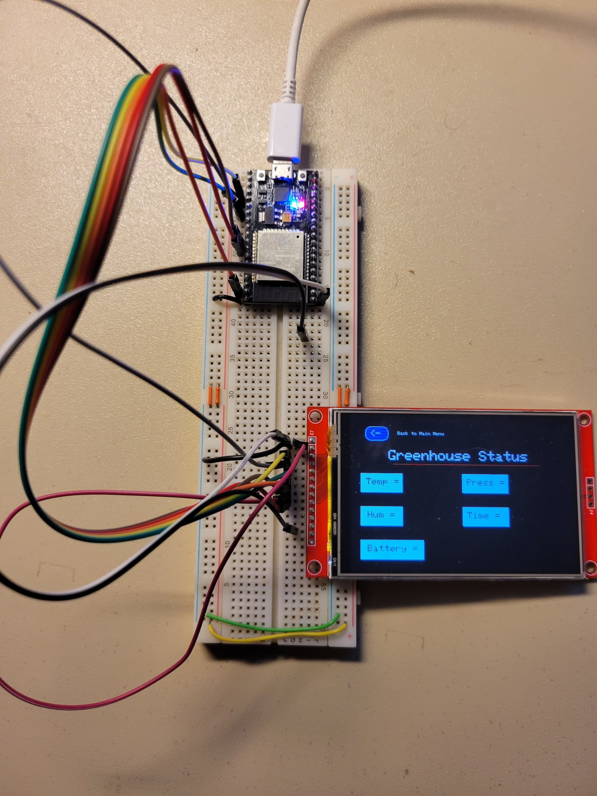
I'm trying to convert a project that I had using a Arduino Mega to a ESP32. I have a remote system in my greenhouse with a BME280 that was sending the values to the Mega via NTF24L01's and displayed on a TFT screen

I am new to ESP32's and also just started using the TFT_eSPI library to update the TFT. Currently I'm just trying to redraw the labels on the screen, not reading or displaying the BME values. I have the labels in a function block "drawGreenhouse1()". I call the function from setup. When I run it the screen blinks on and off. I believe it's doing a "tft.fillScreen(TFT_BLACK);" then my labels. If I comment out the function call and put the label logic in setup it works fine, shows the labels and it's not blinking.

I put a Serial.print("Start SetUp") at the beginning of setup, then uncommented the call to the function and commented out the draw labels in setup. What I see is that setup keeps restarting so I assume for some reason when I call the function it is resetting the ESP32.

I don't know why? Is that what's happening, it's resetting the ESP32 or is it something else?

Here is my sketch


// Changed controller to ESP32

#include <SPI.h>
#include <TFT_eSPI.h> // Hardware-specific library

TFT_eSPI tft = TFT_eSPI();       // Invoke custom library

//==== Defining Variables

unsigned char text;
//char text[6] = "";
String inTemp, inHum, outTemp = "", outHum;
extern uint8_t SmallFont[];
extern uint8_t BigFont[];
extern uint8_t SevenSegNumFont[];

int x, y;

int currentPage = 0; //, selectedUnit;
int selectedUnit = 0;

char grnHouseTemp[20] = " "; // Greenhouse Temperature number
char grnHouseHum[20] = " "; // Greenhouse Humidity number
long int start_time = millis();
long int read_time = 4800; // time between reading Greenhouse data
int grnHouseRead = 0; // bit that system is reading Greenhouse status
float  grnHouse_Temp = 0; // Greenhouse temp
float  grnHouse_Hum = 0; // Greenhouse humdity
float  grnHouse_Press = 0; // Greenhouse pressure
boolean newData = false;

    // temporary array for use when parsing
const byte numChars = 64;
char receivedChars[numChars];
char tempChars[numChars];   

  // For Greenhouse
char temp_str1[25];
char humd_str1[25];
char prss_str1[25];
char Hour_strl[25];
char Min_strl[25];
char Batt_strl[25];

// Incoming data
struct incomingData {
 float In_Temp;
 float In_Prss;
 float In_Humd;
 int   In_Hour;
 int   In_Min;
 float Batt_Lvl;
}myincomingDataStructure;

// data from Greenhouse
struct dataStruct1 {
 float H1_Temp;
 float H1_Prss;
 float H1_Humd;
 float H1_Batt;
}myDataStructure1;

long int touchTime = 0; // time sceen was last touched
long int scrnSavTime = 60000; // Screen saver display time
int scrnSavOn = 0; //In screen saver mode
const int backLite = 53;

void setup() {
  Serial.begin(9600);
  Serial.println("Start Setup");

// TFT setup

  tft.init();
  tft.fillScreen(TFT_BLACK); //clears screen, sets to Black
  tft.setRotation(3);  // rotates screen 180' for landscape mode

  currentPage = 0; // Indicates that we are at Home Screen
  selectedUnit = 0; // Indicates the selected unit for the first example, cms or inches

  //  Serial.println(drawHomeScreen());  // Draws the Home Screen
   drawGreenhouse1();  // Draws the Greenhouse 1 Status screen
   
  // Draw labels from Setup
/*
  tft.fillScreen(TFT_BLACK); 

 // Back to Home button
  
  tft.fillRoundRect(30, 20, 50, 30, 10, TFT_BLUE);
  tft.drawRoundRect(30, 20, 50, 30, 10, TFT_WHITE);
  tft.setCursor(40, 27);
  tft.setTextColor(TFT_WHITE);
  tft.setTextSize(2);
  tft.print("<-"); 

  tft.setCursor(100, 30);
  tft.setTextColor(TFT_WHITE);
  tft.setTextSize(1);
  tft.print("Back to Main Menu"); 

  // Prints the title on the screen
  tft.setCursor(80, 70);
  tft.setTextColor(TFT_WHITE);
  tft.setTextSize(3);
  tft.print("Greenhouse Status"); 

  // Draws the red line under the title
  tft.drawFastHLine(90, 100, 320, TFT_RED);

 // Label - Temperature
  
  tft.fillRect(20, 120, 90, 40, TFT_CYAN);
  tft.drawRect(20, 120, 90, 40, TFT_WHITE);
 // tft.fillRect(0, 0, 90, 40, TFT_CYAN);
 // tft.drawRect(5, 3, 90, 40, TFT_WHITE);
  tft.setCursor(32, 130); 
  tft.setTextColor(TFT_BLACK);
  tft.setTextSize(2);
  tft.print("Temp = "); 
  //tft.drawCentreString("Temp = ",120, 70, 4);

 // Label Humidity #
  
  tft.fillRect(20, 190, 90, 40, TFT_CYAN);
  tft.drawRect(20, 190, 90, 40, TFT_WHITE);
  tft.setCursor(35, 200); 
  tft.setTextColor(TFT_BLACK);
  tft.setTextSize(2);
  tft.print("Hum = "); 

 // Label Pressure
  
  tft.fillRect(240, 120, 100, 40, TFT_CYAN);
  tft.drawRect(240, 120, 100, 40, TFT_WHITE);
  tft.setCursor(250, 130); 
  tft.setTextColor(TFT_BLACK);
  tft.setTextSize(2);
  tft.print("Press = "); 

  // Label Update Time
  
  tft.fillRect(240, 190, 100, 40, TFT_CYAN);
  tft.drawRect(240, 190, 100, 40, TFT_WHITE);
  tft.setCursor(250, 200); 
  tft.setTextColor(TFT_BLACK);
  tft.setTextSize(2);
  tft.print("Time = "); 

  // Label Battery Llevel
  
  tft.fillRect(20, 260, 135, 40, TFT_CYAN);
  tft.drawRect(20, 260, 135, 40, TFT_WHITE);
  tft.setCursor(35, 270); 
  tft.setTextColor(TFT_BLACK);
  tft.setTextSize(2);
  tft.print("Battery = "); 
*/
 
  touchTime = millis(); // start touch time

} // end void setup


void loop() {


} // end void loop


// drawHomeScreen - Menu page

unsigned long drawHomeScreen() {
  // Draws Home Screen
   tft.fillScreen(TFT_BLACK); //clears screen, sets to Black
 
// Prints the title on the screen
  tft.setCursor(80, 70);
  tft.setTextColor(TFT_WHITE);
  tft.setTextSize(3);
  tft.print("Greenhouse Monitor"); 

  // Draws the red line under the title
  tft.drawFastHLine(60, 100, 350, TFT_RED);


  // Button - Greenhouse page
  
  tft.fillRoundRect(140, 150, 210, 40, 25, TFT_BLUE);
  tft.drawRoundRect(140, 150, 210, 40, 25, TFT_WHITE);
  tft.setCursor(170, 160);
  tft.setTextColor(TFT_WHITE);
  tft.setTextSize(2);
  tft.print("Greenhouse"); 

 } // end void drawHomeScreen

unsigned long drawGreenhouse1() {
  // Draws Report Setup screen
  Serial.println("In drawGreenhouse1");
  // Sets the background color of the screen to black
  tft.fillScreen(TFT_BLACK); 

 // Back to Home button
  
  tft.fillRoundRect(30, 20, 50, 30, 10, TFT_BLUE);
  tft.drawRoundRect(30, 20, 50, 30, 10, TFT_WHITE);
  tft.setCursor(40, 27);
  tft.setTextColor(TFT_WHITE);
  tft.setTextSize(2);
  tft.print("<-"); 

  tft.setCursor(100, 30);
  tft.setTextColor(TFT_WHITE);
  tft.setTextSize(1);
  tft.print("Back to Main Menu"); 

  // Prints the title on the screen
  tft.setCursor(80, 70);
  tft.setTextColor(TFT_WHITE);
  tft.setTextSize(3);
  tft.print("Greenhouse Status"); 

  // Draws the red line under the title
  tft.drawFastHLine(90, 100, 320, TFT_RED);

 // Label - Temperature
  
  tft.fillRect(20, 120, 90, 40, TFT_CYAN);
  tft.drawRect(20, 120, 90, 40, TFT_WHITE);
 // tft.fillRect(0, 0, 90, 40, TFT_CYAN);
 // tft.drawRect(5, 3, 90, 40, TFT_WHITE);
  tft.setCursor(32, 130); 
  tft.setTextColor(TFT_BLACK);
  tft.setTextSize(2);
  tft.print("Temp = "); 
  //tft.drawCentreString("Temp = ",120, 70, 4);

 // Label Humidity #
  
  tft.fillRect(20, 190, 90, 40, TFT_CYAN);
  tft.drawRect(20, 190, 90, 40, TFT_WHITE);
  tft.setCursor(35, 200); 
  tft.setTextColor(TFT_BLACK);
  tft.setTextSize(2);
  tft.print("Hum = "); 

 // Label Pressure
  
  tft.fillRect(240, 120, 100, 40, TFT_CYAN);
  tft.drawRect(240, 120, 100, 40, TFT_WHITE);
  tft.setCursor(250, 130); 
  tft.setTextColor(TFT_BLACK);
  tft.setTextSize(2);
  tft.print("Press = "); 

  // Label Update Time
  
  tft.fillRect(240, 190, 100, 40, TFT_CYAN);
  tft.drawRect(240, 190, 100, 40, TFT_WHITE);
  tft.setCursor(250, 200); 
  tft.setTextColor(TFT_BLACK);
  tft.setTextSize(2);
  tft.print("Time = "); 

  // Label Battery Llevel
  
  tft.fillRect(20, 260, 135, 40, TFT_CYAN);
  tft.drawRect(20, 260, 135, 40, TFT_WHITE);
  tft.setCursor(35, 270); 
  tft.setTextColor(TFT_BLACK);
  tft.setTextSize(2);
  tft.print("Battery = "); 

} // end of drawGreenhouse1

Thanks for any comments or suggestions
John

Pin out connection of the tft?

You write the library?

@Idahowalker Here's the pinouts to the TFT

#define TFT_MISO 19
#define TFT_MOSI 23
#define TFT_SCLK 18
#define TFT_CS 15 // Chip select control pin
#define TFT_DC 2 // Data Command control pin
#define TFT_RST 4 // Reset pin (could connect to RST pin)
VCC and LED are to 3.3V pin on the ESP32 and Gnd to GND

and it's driver is
#define ILI9488_DRIVER

These are defined in the "User_Setup.h" file in the TFT_ESPI library. You have to uncomment lines to match your TFT. Here is the file as I have it set up

//                            USER DEFINED SETTINGS
//   Set driver type, fonts to be loaded, pins used and SPI control method etc
//
//   See the User_Setup_Select.h file if you wish to be able to define multiple
//   setups and then easily select which setup file is used by the compiler.
//
//   If this file is edited correctly then all the library example sketches should
//   run without the need to make any more changes for a particular hardware setup!
//   Note that some sketches are designed for a particular TFT pixel width/height


// ##################################################################################
//
// Section 1. Call up the right driver file and any options for it
//
// ##################################################################################

// Define STM32 to invoke optimised processor support (only for STM32)
//#define STM32

// Defining the STM32 board allows the library to optimise the performance
// for UNO compatible "MCUfriend" style shields
//#define NUCLEO_64_TFT
//#define NUCLEO_144_TFT

// STM32 8 bit parallel only:
// If STN32 Port A or B pins 0-7 are used for 8 bit parallel data bus bits 0-7
// then this will improve rendering performance by a factor of ~8x
//#define STM_PORTA_DATA_BUS
//#define STM_PORTB_DATA_BUS

// Tell the library to use 8 bit parallel mode (otherwise SPI is assumed)
//#define TFT_PARALLEL_8_BIT

// Display type -  only define if RPi display
//#define RPI_DISPLAY_TYPE // 20MHz maximum SPI

// Only define one driver, the other ones must be commented out
//#define ILI9341_DRIVER       // Generic driver for common displays
//#define ILI9341_2_DRIVER     // Alternative ILI9341 driver, see https://github.com/Bodmer/TFT_eSPI/issues/1172
//#define ST7735_DRIVER      // Define additional parameters below for this display
//#define ILI9163_DRIVER     // Define additional parameters below for this display
//#define S6D02A1_DRIVER
//#define RPI_ILI9486_DRIVER // 20MHz maximum SPI
//#define HX8357D_DRIVER
//#define ILI9481_DRIVER
//#define ILI9486_DRIVER
#define ILI9488_DRIVER     // WARNING: Do not connect ILI9488 display SDO to MISO if other devices share the SPI bus (TFT SDO does NOT tristate when CS is high)
//#define ST7789_DRIVER      // Full configuration option, define additional parameters below for this display
//#define ST7789_2_DRIVER    // Minimal configuration option, define additional parameters below for this display
//#define R61581_DRIVER
//#define RM68140_DRIVER
//#define ST7796_DRIVER
//#define SSD1351_DRIVER
//#define SSD1963_480_DRIVER
//#define SSD1963_800_DRIVER
//#define SSD1963_800ALT_DRIVER
//#define ILI9225_DRIVER
//#define GC9A01_DRIVER

// Some displays support SPI reads via the MISO pin, other displays have a single
// bi-directional SDA pin and the library will try to read this via the MOSI line.
// To use the SDA line for reading data from the TFT uncomment the following line:

// #define TFT_SDA_READ      // This option is for ESP32 ONLY, tested with ST7789 and GC9A01 display only

// For ST7735, ST7789 and ILI9341 ONLY, define the colour order IF the blue and red are swapped on your display
// Try ONE option at a time to find the correct colour order for your display

//  #define TFT_RGB_ORDER TFT_RGB  // Colour order Red-Green-Blue
//  #define TFT_RGB_ORDER TFT_BGR  // Colour order Blue-Green-Red

// For M5Stack ESP32 module with integrated ILI9341 display ONLY, remove // in line below

// #define M5STACK

// For ST7789, ST7735, ILI9163 and GC9A01 ONLY, define the pixel width and height in portrait orientation
// #define TFT_WIDTH  80
// #define TFT_WIDTH  128
// #define TFT_WIDTH  240 // ST7789 240 x 240 and 240 x 320
// #define TFT_HEIGHT 160
// #define TFT_HEIGHT 128
// #define TFT_HEIGHT 240 // ST7789 240 x 240
// #define TFT_HEIGHT 320 // ST7789 240 x 320
// #define TFT_HEIGHT 240 // GC9A01 240 x 240

// For ST7735 ONLY, define the type of display, originally this was based on the
// colour of the tab on the screen protector film but this is not always true, so try
// out the different options below if the screen does not display graphics correctly,
// e.g. colours wrong, mirror images, or stray pixels at the edges.
// Comment out ALL BUT ONE of these options for a ST7735 display driver, save this
// this User_Setup file, then rebuild and upload the sketch to the board again:

// #define ST7735_INITB
// #define ST7735_GREENTAB
// #define ST7735_GREENTAB2
// #define ST7735_GREENTAB3
// #define ST7735_GREENTAB128    // For 128 x 128 display
// #define ST7735_GREENTAB160x80 // For 160 x 80 display (BGR, inverted, 26 offset)
// #define ST7735_REDTAB
// #define ST7735_BLACKTAB
// #define ST7735_REDTAB160x80   // For 160 x 80 display with 24 pixel offset

// If colours are inverted (white shows as black) then uncomment one of the next
// 2 lines try both options, one of the options should correct the inversion.

// #define TFT_INVERSION_ON
// #define TFT_INVERSION_OFF


// ##################################################################################
//
// Section 2. Define the pins that are used to interface with the display here
//
// ##################################################################################

// If a backlight control signal is available then define the TFT_BL pin in Section 2
// below. The backlight will be turned ON when tft.begin() is called, but the library
// needs to know if the LEDs are ON with the pin HIGH or LOW. If the LEDs are to be
// driven with a PWM signal or turned OFF/ON then this must be handled by the user
// sketch. e.g. with digitalWrite(TFT_BL, LOW);

// #define TFT_BL   32            // LED back-light control pin
// #define TFT_BACKLIGHT_ON HIGH  // Level to turn ON back-light (HIGH or LOW)


// We must use hardware SPI, a minimum of 3 GPIO pins is needed.
// Typical setup for ESP8266 NodeMCU ESP-12 is :
//
// Display SDO/MISO  to NodeMCU pin D6 (or leave disconnected if not reading TFT)
// Display LED       to NodeMCU pin VIN (or 5V, see below)
// Display SCK       to NodeMCU pin D5
// Display SDI/MOSI  to NodeMCU pin D7
// Display DC (RS/AO)to NodeMCU pin D3
// Display RESET     to NodeMCU pin D4 (or RST, see below)
// Display CS        to NodeMCU pin D8 (or GND, see below)
// Display GND       to NodeMCU pin GND (0V)
// Display VCC       to NodeMCU 5V or 3.3V
//
// The TFT RESET pin can be connected to the NodeMCU RST pin or 3.3V to free up a control pin
//
// The DC (Data Command) pin may be labelled AO or RS (Register Select)
//
// With some displays such as the ILI9341 the TFT CS pin can be connected to GND if no more
// SPI devices (e.g. an SD Card) are connected, in this case comment out the #define TFT_CS
// line below so it is NOT defined. Other displays such at the ST7735 require the TFT CS pin
// to be toggled during setup, so in these cases the TFT_CS line must be defined and connected.
//
// The NodeMCU D0 pin can be used for RST
//
//
// Note: only some versions of the NodeMCU provide the USB 5V on the VIN pin
// If 5V is not available at a pin you can use 3.3V but backlight brightness
// will be lower.


// ###### EDIT THE PIN NUMBERS IN THE LINES FOLLOWING TO SUIT YOUR ESP8266 SETUP ######

// For NodeMCU - use pin numbers in the form PIN_Dx where Dx is the NodeMCU pin designation
//#define TFT_CS   PIN_D8  // Chip select control pin D8
//#define TFT_DC   PIN_D3  // Data Command control pin D3
//#define TFT_RST  PIN_D4  // Reset pin (could connect to NodeMCU RST, see next line)
//#define TFT_RST  -1    // Set TFT_RST to -1 if the display RESET is connected to NodeMCU RST or 3.3V

//#define TFT_BL PIN_D1  // LED back-light (only for ST7789 with backlight control pin)

//#define TOUCH_CS PIN_D2     // Chip select pin (T_CS) of touch screen

//#define TFT_WR PIN_D2       // Write strobe for modified Raspberry Pi TFT only


// ######  FOR ESP8266 OVERLAP MODE EDIT THE PIN NUMBERS IN THE FOLLOWING LINES  ######

// Overlap mode shares the ESP8266 FLASH SPI bus with the TFT so has a performance impact
// but saves pins for other functions. It is best not to connect MISO as some displays
// do not tristate that line when chip select is high!
// Note: Only one SPI device can share the FLASH SPI lines, so a SPI touch controller
// cannot be connected as well to the same SPI signals.
// On NodeMCU 1.0 SD0=MISO, SD1=MOSI, CLK=SCLK to connect to TFT in overlap mode
// On NodeMCU V3  S0 =MISO, S1 =MOSI, S2 =SCLK
// In ESP8266 overlap mode the following must be defined

//#define TFT_SPI_OVERLAP

// In ESP8266 overlap mode the TFT chip select MUST connect to pin D3
//#define TFT_CS   PIN_D3
//#define TFT_DC   PIN_D5  // Data Command control pin
//#define TFT_RST  PIN_D4  // Reset pin (could connect to NodeMCU RST, see next line)
//#define TFT_RST  -1  // Set TFT_RST to -1 if the display RESET is connected to NodeMCU RST or 3.3V


// ###### EDIT THE PIN NUMBERS IN THE LINES FOLLOWING TO SUIT YOUR ESP32 SETUP   ######

// For ESP32 Dev board (only tested with ILI9341 display)
// The hardware SPI can be mapped to any pins

#define TFT_MISO 19
#define TFT_MOSI 23
#define TFT_SCLK 18
#define TFT_CS   15  // Chip select control pin
#define TFT_DC    2  // Data Command control pin
#define TFT_RST   4  // Reset pin (could connect to RST pin)
//#define TFT_RST  -1  // Set TFT_RST to -1 if display RESET is connected to ESP32 board RST

// For ESP32 Dev board (only tested with GC9A01 display)
// The hardware SPI can be mapped to any pins

//#define TFT_MOSI 15 // In some display driver board, it might be written as "SDA" and so on.
//#define TFT_SCLK 14
//#define TFT_CS   5  // Chip select control pin
//#define TFT_DC   27  // Data Command control pin
//#define TFT_RST  33  // Reset pin (could connect to Arduino RESET pin)
//#define TFT_BL   22  // LED back-light

//#define TOUCH_CS 21     // Chip select pin (T_CS) of touch screen

//#define TFT_WR 22    // Write strobe for modified Raspberry Pi TFT only

// For the M5Stack module use these #define lines
//#define TFT_MISO 19
//#define TFT_MOSI 23
//#define TFT_SCLK 18
//#define TFT_CS   14  // Chip select control pin
//#define TFT_DC   27  // Data Command control pin
//#define TFT_RST  33  // Reset pin (could connect to Arduino RESET pin)
//#define TFT_BL   32  // LED back-light (required for M5Stack)

// ######       EDIT THE PINs BELOW TO SUIT YOUR ESP32 PARALLEL TFT SETUP        ######

// The library supports 8 bit parallel TFTs with the ESP32, the pin
// selection below is compatible with ESP32 boards in UNO format.
// Wemos D32 boards need to be modified, see diagram in Tools folder.
// Only ILI9481 and ILI9341 based displays have been tested!

// Parallel bus is only supported for the STM32 and ESP32
// Example below is for ESP32 Parallel interface with UNO displays

// Tell the library to use 8 bit parallel mode (otherwise SPI is assumed)
//#define TFT_PARALLEL_8_BIT

// The ESP32 and TFT the pins used for testing are:
//#define TFT_CS   33  // Chip select control pin (library pulls permanently low
//#define TFT_DC   15  // Data Command control pin - must use a pin in the range 0-31
//#define TFT_RST  32  // Reset pin, toggles on startup

//#define TFT_WR    4  // Write strobe control pin - must use a pin in the range 0-31
//#define TFT_RD    2  // Read strobe control pin

//#define TFT_D0   12  // Must use pins in the range 0-31 for the data bus
//#define TFT_D1   13  // so a single register write sets/clears all bits.
//#define TFT_D2   26  // Pins can be randomly assigned, this does not affect
//#define TFT_D3   25  // TFT screen update performance.
//#define TFT_D4   17
//#define TFT_D5   16
//#define TFT_D6   27
//#define TFT_D7   14

// ######       EDIT THE PINs BELOW TO SUIT YOUR STM32 SPI TFT SETUP        ######

// The TFT can be connected to SPI port 1 or 2
//#define TFT_SPI_PORT 1 // SPI port 1 maximum clock rate is 55MHz
//#define TFT_MOSI PA7
//#define TFT_MISO PA6
//#define TFT_SCLK PA5

//#define TFT_SPI_PORT 2 // SPI port 2 maximum clock rate is 27MHz
//#define TFT_MOSI PB15
//#define TFT_MISO PB14
//#define TFT_SCLK PB13

// Can use Ardiuno pin references, arbitrary allocation, TFT_eSPI controls chip select
//#define TFT_CS   D5 // Chip select control pin to TFT CS
//#define TFT_DC   D6 // Data Command control pin to TFT DC (may be labelled RS = Register Select)
//#define TFT_RST  D7 // Reset pin to TFT RST (or RESET)
// OR alternatively, we can use STM32 port reference names PXnn
//#define TFT_CS   PE11 // Nucleo-F767ZI equivalent of D5
//#define TFT_DC   PE9  // Nucleo-F767ZI equivalent of D6
//#define TFT_RST  PF13 // Nucleo-F767ZI equivalent of D7

//#define TFT_RST  -1   // Set TFT_RST to -1 if the display RESET is connected to processor reset
                        // Use an Arduino pin for initial testing as connecting to processor reset
                        // may not work (pulse too short at power up?)

// ##################################################################################
//
// Section 3. Define the fonts that are to be used here
//
// ##################################################################################

// Comment out the #defines below with // to stop that font being loaded
// The ESP8366 and ESP32 have plenty of memory so commenting out fonts is not
// normally necessary. If all fonts are loaded the extra FLASH space required is
// about 17Kbytes. To save FLASH space only enable the fonts you need!

#define LOAD_GLCD   // Font 1. Original Adafruit 8 pixel font needs ~1820 bytes in FLASH
#define LOAD_FONT2  // Font 2. Small 16 pixel high font, needs ~3534 bytes in FLASH, 96 characters
#define LOAD_FONT4  // Font 4. Medium 26 pixel high font, needs ~5848 bytes in FLASH, 96 characters
#define LOAD_FONT6  // Font 6. Large 48 pixel font, needs ~2666 bytes in FLASH, only characters 1234567890:-.apm
#define LOAD_FONT7  // Font 7. 7 segment 48 pixel font, needs ~2438 bytes in FLASH, only characters 1234567890:-.
#define LOAD_FONT8  // Font 8. Large 75 pixel font needs ~3256 bytes in FLASH, only characters 1234567890:-.
//#define LOAD_FONT8N // Font 8. Alternative to Font 8 above, slightly narrower, so 3 digits fit a 160 pixel TFT
#define LOAD_GFXFF  // FreeFonts. Include access to the 48 Adafruit_GFX free fonts FF1 to FF48 and custom fonts

// Comment out the #define below to stop the SPIFFS filing system and smooth font code being loaded
// this will save ~20kbytes of FLASH
#define SMOOTH_FONT


// ##################################################################################
//
// Section 4. Other options
//
// ##################################################################################

// For RP2040 processor and SPI displays, uncomment the following line to use the PIO interface.
//#define RP2040_PIO_SPI // Leave commented out to use standard RP2040 SPI port interface

// For the RP2040 processor define the SPI port channel used (default 0 if undefined)
//#define TFT_SPI_PORT 1 // Set to 0 if SPI0 pins are used, or 1 if spi1 pins used

// For the STM32 processor define the SPI port channel used (default 1 if undefined)
//#define TFT_SPI_PORT 2 // Set to 1 for SPI port 1, or 2 for SPI port 2

// Define the SPI clock frequency, this affects the graphics rendering speed. Too
// fast and the TFT driver will not keep up and display corruption appears.
// With an ILI9341 display 40MHz works OK, 80MHz sometimes fails
// With a ST7735 display more than 27MHz may not work (spurious pixels and lines)
// With an ILI9163 display 27 MHz works OK.

// #define SPI_FREQUENCY   1000000
// #define SPI_FREQUENCY   5000000
// #define SPI_FREQUENCY  10000000
// #define SPI_FREQUENCY  20000000
#define SPI_FREQUENCY  27000000
// #define SPI_FREQUENCY  40000000
// #define SPI_FREQUENCY  55000000 // STM32 SPI1 only (SPI2 maximum is 27MHz)
// #define SPI_FREQUENCY  80000000

// Optional reduced SPI frequency for reading TFT
#define SPI_READ_FREQUENCY  20000000

// The XPT2046 requires a lower SPI clock rate of 2.5MHz so we define that here:
#define SPI_TOUCH_FREQUENCY  2500000

// The ESP32 has 2 free SPI ports i.e. VSPI and HSPI, the VSPI is the default.
// If the VSPI port is in use and pins are not accessible (e.g. TTGO T-Beam)
// then uncomment the following line:
//#define USE_HSPI_PORT

// Comment out the following #define if "SPI Transactions" do not need to be
// supported. When commented out the code size will be smaller and sketches will
// run slightly faster, so leave it commented out unless you need it!

// Transaction support is needed to work with SD library but not needed with TFT_SdFat
// Transaction support is required if other SPI devices are connected.

// Transactions are automatically enabled by the library for an ESP32 (to use HAL mutex)
// so changing it here has no effect

// #define SUPPORT_TRANSACTIONS


LOL, I'm not smart enough to write my own library, I copied that line, and a few others, from one of the examples that came with the TFT_eSPI library.

Thanks

The code posted in post#1 does not contain the above information. Please post the code you are using.

Have you tied the backlight pin to VCC?

Post an image of your project all wired up and under power.

Is this the same post, Function call resetting ESP32 - Using Arduino / Programming Questions - Arduino Forum? Why make multiple postings?

@Idahowalker I only made one post, not sure why you're seeing it in multiple places.

To use the TFT_eSPI you don't define the pins in your sketch there is a text file called "User_Setup.h" in the library, you define everything in that file. It has definitions for multiple TFT drivers and boards, you uncomment the relevant ones for your system. The way I have it is the second file I attached.

Here is a picture of the board and TFT, I've loaded the screen from the setup and commented out the call to the function, this is how it should look when called from the function but it appears to be resetting the ESP when I call the function.

Thanks for looking into this for me.

@Idahowalker was just thinking about the multiple post. I had a post yesterday about how to set up communications between 2 ESP32's. You answered that and told me how you have a RPi as a server to your multiple ESP's. This new post is for the same project but a different problem and a different post.

Thanks again

@Idahowalker

Unless you are seeing something different than me, the topic that you posted a link to is, in fact, this topic

Did you post the correct link ?

I used the wrong link and lost track of what I thought was the original posting. My error.

OK, the connections look good, the code produces a screen.

When you set tools core debug to debug does the ESP32 produce a printout when the thing goes wonky?

I'm guessing the vReg of the ESP32 does not have enough oomph to keep up with the tft needs. Try adding a 3.3V regulator off the 5V. Try adding a large electrolytic cap, 470uF, off the 3.3V line with a 103 ceramic.

I'll give that a try, won't be for a few hours I had some errands to run.

That would explain the resetting. If the 3.3v doesn't have enough power why does it work when I load the screen from setup as opposed to calling the function from setup?

Would connecting it to 5v make a difference? Should I use a separate power supply for the TFT? Maybe a different type of display.

Thanks again