Esp32 WDT triggered

Hi,
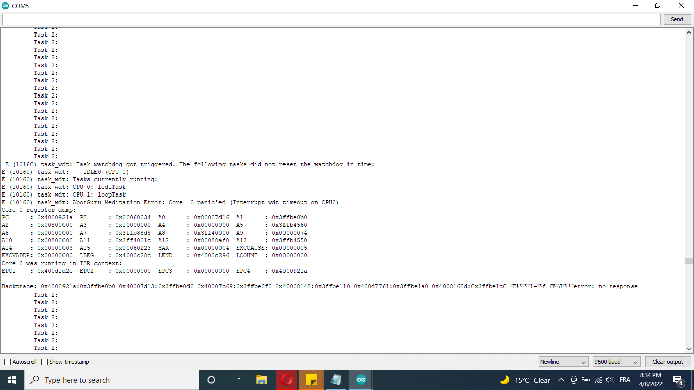
I am using Arduino EsP32 to balance a ball on plate, I am trying to use ESP32 with both Core 0 and core 1, the problem is that WDT is triggering.
the code is here:

#include <SCServo.h>
#include <math.h>
#include "fis_header.h"
#include <PID_v1.h>
#include <Pixy2.h>

//For Serial 1
#define TX1_pin  26
#define RX1_pin  27

//For Serial 2
#define RXD2 16
#define TXD2 17


Pixy2 pixy;
SCSCL sc;


int S1M = 300;
int S2M = 300;
int S3M = 300;

int  input = 0;
float angles[3];


TaskHandle_t Task1, Task2, Task3;
SemaphoreHandle_t baton;


int counter = 0;


float Roll_i;
float Pitch_i;
int X, Y, blocks, t = 0;
float ErY;


void blink(byte pin, int duration) {

  digitalWrite(pin, HIGH);
  delay(duration);
  digitalWrite(pin, LOW);
  delay(duration);
}


double SetpointX, InputX, OutputX;
double SetpointY, InputY, OutputY;


double KpX = 3.7589, KiX = 01.24, KdX = 1.58;
double KpY = 3.7589, KiY = 01.24, KdY = 1.58;


PID myPID(&InputX, &OutputX, &SetpointX, KpX, KiX, KdX, DIRECT);
PID myPID1(&InputY, &OutputY, &SetpointY, KpY, KiY, KdY, DIRECT);

float usecLst = 0, errLst = 0, posLst = 0, pos = 0, errX = 0, dErr = 0;
unsigned long usec, dT;

double k = 0;
int x = 0;                      //positon x axis
int y = 0;                      //position y axis
int z = 0;

int Xmax = 234;
int Ymax = 200;

int Roll;
int Pitch;


//----------------------Attachements coordinates-----------------------
//Base attachements coordinates
float b[][3] = {{4,    -2.0,       -2.0},
  {0,     4.89,    -4.89},
  {0.0,   0.0,       0.0}
};


//Plate attachements coordinates
float p[][3] = {{4.5,       -2.25,        -2.25},
  {0.0,        5.51,        -5.51},
  {0.0,         0.0,          0.0}
};


//----------------- CONSTANTS NEEDED FOR COMPUTATION OBTAINED FROM DESIGN STAGE IN MATLAB ----------------------------

float s = 6;    //length of connection links
float a = 3;  //length of servo horn
float h0 = 6.6895; //"home" height of the platform relative to the base
float  errLstX = 0, errLstY = 0, posX = 0, posY = 0, errY = 0, dErrX = 0, dErrY = 0;


void codeForTask3( void * parameter )
{
  for (;;) {
    delay(50);
  }
}


void codeForTask1( void * parameter )
{
  for (;;) {


    S1M = map((angles[0]  * 57.29) + 50 , 0, 300, 0, 1022);
    S2M = map((angles[1]  * 57.29) + 50 , 0, 300, 0, 1022);
    S3M = map((angles[2]  * 57.29) + 50 , 0, 300, 0, 1022);

    S1M = S1M - 5;
    S2M = S2M - 80;
    S3M = S3M - 5;
    if (S1M > 425)
      S1M = 425;
    if (S2M > 350)
      S2M = 350;
    if (S3M > 425)
      S3M = 425;

    if (S1M < 150)
      S1M = 150;
    if (S2M < 150)
      S2M = 150;
    if (S3M < 150)
      S3M = 150;

    //---------------------------------------- Move Servos ----------------------------------------------------------------

    sc.WritePos(3, S1M, 0);
    sc.WritePos(2, S2M, 0);
    sc.WritePos(1, S3M, 0);
    //delay(50);
    // Serial.println("Task 1: ");

  }
}

void codeForTask2( void * parameter )
{
  for (;;) {

    int j;
    // grab blocks!
    pixy.ccc.getBlocks();
    if (pixy.ccc.numBlocks)
    {
      for (j = 0; j < pixy.ccc.numBlocks; j++)
      {
        X = pixy.ccc.blocks[j].m_x; //Getting Ball Coordinate X
        Y = pixy.ccc.blocks[j].m_x;    //Getting Ball Coordinate Y
      }

    }

    //From pixels to cm
    InputX = X * 0.168;
    InputY = Y * 0.154;


    myPID.Compute();
    myPID1.Compute();
    Roll  = OutputX;
    Pitch = OutputY;

    Roll_i = Roll * 0.017;
    Pitch_i = Pitch * 0.017; //20 * sin(k)*0.017; // ((20 * cos(k)) / (1 + sin(k) * sin(k)))*0.017; //20 * sin(k)*0.017; ////// //;  //Pitch
    float phi   = Roll_i;//;20
    float theta = Pitch_i;//;
    float psi   = 0;

    //compute rotation matrix for the planned euler sequence
    float R[][3] = {{ cos(psi)*cos(theta),    (-sin(psi)*cos(phi)) + (cos(psi)*sin(theta)*sin(phi)),    ( sin(psi)*sin(phi)) + (cos(psi)*sin(theta)*cos(phi)) },
      {sin(psi)*cos(theta),    ( cos(psi)*cos(phi)) + (sin(psi)*sin(theta)*sin(phi)),    (-cos(psi)*sin(phi)) + (sin(psi)*sin(theta)*cos(phi)) },
      { -sin(theta),               cos(theta)*sin(phi),                                                      cos(theta)*cos(phi) }
    };
    //
    //
    //  Serial.print("\nR = \n");
    //  printvector(R);

    //compute the translation vector
    float T[] = {x, y, (z + h0)};

    //Serial.print("\nT = \n");
    //printvector(&T[0], 3);


    //compute the vector q = T + R*p for the location of the connections in the base frame
    int i;
    float q[3][3];
    for (i = 0; i < 3; i++)
    {
      q[0][i] = (T[0]) +   R[0][0] * p[0][i]       + R[0][1]  * p[1][i]       + R[0][2] * p[2][i] ;
      q[1][i] = (T[1]) +   R[1][0] * p[0][i]       + R[1][1]  * p[1][i]       + R[1][2] * p[2][i];
      q[2][i] = (T[2]) +   R[2][0] * p[0][i]       + R[2][1]  * p[1][i]       + R[2][2] * p[2][i];
    }

    //  Serial.print("\nq = \n");
    //  printvector(q);

    //compute the necessary leg lengths (the distance from b to q) and save it as l for each servo. Take the norm to do it.
    float l[3];
    for (i = 0; i < 3; i++)
    {
      l[i] = sqrt(((q[0][i] - b[0][i]) * (q[0][i] - b[0][i])) + ((q[1][i] - b[1][i]) * (q[1][i] - b[1][i])) + ((q[2][i] - b[2][i]) * (q[2][i] - b[2][i])));
    }

    //Serial.print("\nl = \n");
    //  printvector(&l[0], 3);

    //use trigonometry and the other constants you know to extract the angle of each servo

    // float A[3]={cos(a11),cos(12),cos(13)};
    for (i = 0; i < 3; i++)
    {
      angles[i] = acos(((l[i] * l[i]) - 27) / (l[i] * 6));
      // angles[i] = 3.14 - asin(0.04 / l[i]) - acos(((l[i] * l[i]) - 27) / (l[i] * 6));
    }
    //Serial.println("             Task 2: ");
    Serial.println("         Task 2: ");
  }
}


// the setup function runs once when you press reset or power the board
void setup() {
  Serial.begin(9600);
  // initialize digital pin LED_BUILTIN as an output.
  Serial2.begin(9600, SERIAL_8N1, RXD2, TXD2);    //For the camera
  pinMode(LED1, OUTPUT);
  pinMode(LED2, OUTPUT);
  Serial1.begin(1000000, SERIAL_8N1, RX1_pin, TX1_pin);
  sc.pSerial = &Serial1;
  pixy.init();
  pixy.setLamp(1, 0);

  SetpointX = 19; //cm //85 + (50 * cos(k)) / (1 + sin(k) * sin(k));//
  SetpointY = 15;//cm // 55 + (50 * sin(k) * cos(k)) / (1 + sin(k) * sin(k));//

  myPID.SetMode(AUTOMATIC);
  myPID.SetOutputLimits(-8, 8);
  myPID1.SetMode(AUTOMATIC);
  myPID1.SetOutputLimits(-8, 8);
  myPID1.SetSampleTime(20);
  myPID.SetSampleTime(20);

  xTaskCreatePinnedToCore(
    codeForTask1,
    "led1Task",
    1000,
    NULL,
    2,
    &Task1,
    0);
  delay(500);  // needed to start-up task1

  xTaskCreatePinnedToCore(
    codeForTask2,
    "led2Task",
    1000,
    NULL,
    3,
    &Task2,
    1);
  delay(500);  // needed to start-up task1

  xTaskCreatePinnedToCore(
    codeForTask3,
    "led3Task",
    1000,
    NULL,
    1,
    &Task3,
    0);
}

void loop() {
  // Serial.println(InputX);
  delay(1);
}

and here are the decoding errors:

*Decoding stack results* 0x4008b54c: **invoke_abort** at /Users/ficeto/Desktop/ESP32/ESP32/esp-idf-public/components/esp32/**panic.c** line **155** 0x4008b779: **abort** at /Users/ficeto/Desktop/ESP32/ESP32/esp-idf-public/components/esp32/**panic.c** line **170** 0x400d77eb: **task_wdt_isr** at /Users/ficeto/Desktop/ESP32/ESP32/esp-idf-public/components/esp32/**task_wdt.c** line **174** 0x40081127: **millis** at C:\Users\Oussama HADOUNE\AppData\Local\Arduino15\packages\esp32\hardware\esp32\1.0.3-rc3\cores\esp32\**esp32-hal-misc.c** line **139** 0x400d1da7: **SCSerial::readSCS(unsigned char*, int)** at C:\Users\Oussama HADOUNE\Documents\Arduino\libraries\SCServo-master\**SCSerial.cpp** line **47** 0x400ec876: **SCS::checkHead()** at C:\Users\Oussama HADOUNE\Documents\Arduino\libraries\SCServo-master\**SCS.cpp** line **264** 0x400d18de: **SCS::Ack(unsigned char)** at C:\Users\Oussama HADOUNE\Documents\Arduino\libraries\SCServo-master\**SCS.cpp** line **284** 0x400d1951: **SCS::genWrite(unsigned char, unsigned char, unsigned char*, unsigned char)** at C:\Users\Oussama HADOUNE\Documents\Arduino\libraries\SCServo-master\**SCS.cpp** line **98** 0x400d1a01: **SCSCL::WritePos(unsigned char, unsigned short, unsigned short, unsigned short)** at C:\Users\Oussama HADOUNE\Documents\Arduino\libraries\SCServo-master\**SCSCL.cpp** line **30** 0x400d1796: **codeForTask1(void*)** at C:\Users\Oussama HADOUNE\Documents\Arduino\test_Dual_Cores/**test_Dual_Cores.ino** line **153** 0x4008a099: **vPortTaskWrapper** at /Users/ficeto/Desktop/ESP32/ESP32/esp-idf-public/components/freertos/**port.c** line **143**

That's what's shown in the Serial monitor:

        Task 2: 
         Task 2: 
         Task 2: 
         Task 2: 
         Task 2: 
         Task 2: 
         Task 2: 
         Task 2: 
         Task 2: 
         Task 2: 
         Task 2: 
         Task 2: 
         Task 2: 
         Task 2: 
         Task 2: 
         Task 2: 
         Task 2: 
         Task 2: 
         Task 2: 
         Task 2: 
         Task 2: 
         Task 2: 
         Task 2: 
         Task 2: 
         Task 2: 
         Task 2: 
         Task 2: 
         Task 2: 
         Task 2: 
         Task 2: 
         Task 2: 
         Task 2: 
         Task 2: 
         Task 2: 
         Task 2: 
         Task 2: 
         Task 2: 
         Task 2: 
         Task 2: 
         Task 2: 
         Task 2: 
         Task 2: 
         Task 2: 
         Task 2: 
         Task 2: 
         Task 2: 
         Task 2: 
         Task 2: 
         Task 2: 
         Task 2: 
 E (10160) task_wdt: Task watchdog got triggered. The following tasks did not reset the watchdog in time:
E (10160) task_wdt:  - IDLE0 (CPU 0)
E (10160) task_wdt: Tasks currently running:
E (10160) task_wdt: CPU 0: led1Task
E (10160) task_wdt: CPU 1: led2Task
E (10160) task_wdt: AborGuru Meditation Error: Core  0 panic'ed (Interrupt wdt timeout on CPU0)
Core 0 register dump:
PC      : 0x4000921a  PS      : 0x00060034  A0      : 0x80007d16  A1      : 0x3ffbe0b0  
A2      : 0x00800000  A3      : 0x10000000  A4      : 0x00000000  A5      : 0x3ffb8b00  
A6      : 0x3ffc053c  A7      : 0x00000000  A8      : 0x3ff40000  A9      : 0x00000074  
A10     : 0x00800000  A11     : 0x3ff4001c  A12     : 0x800d2bf8  A13     : 0x3ffb8ae0  
A14     : 0x3ffbecb0  A15     : 0xc3400000  SAR     : 0x00000004  EXCCAUSE: 0x00000005  
EXCVADDR: 0x00000000  LBEG    : 0x4000c28c  LEND    : 0x4000c296  LCOUNT  : 0x00000000  
Core 0 was running in ISR context:
EPC1    : 0x40088af0  EPC2    : 0x00000000  EPC3    : 0x00000000  EPC4    : 0x4000921a

Backtrace: 0x4000921a:0x3ffbe0b0 0x40007d13:0x3ffbe0d0 0x40007c69:0x3ffbe0f0 0x40008148:0x3ffbe110 0x400d77d5:0x3ffbe1a0 0x4008168d:0x3ffbe1c0 N⸮1⸮⸮⸮⸮⸮⸮	%⸮⸮⸮⸮⸮⸮error: no response
         Task 2: 
         Task 2: 
         Task 2: 
         Task 2: 
         Task 2: 
         Task 2: 
         Task 2: 
         Task 2: 
         Task 2: 
         Task 2: 
         Task 2: 
         Task 2: 
         Task 2: 
         Task 2: 
         Task 2: 
         Task 2: 
         Task 2: 
         Task 2: 
         Task 2: 

How did you prove that your tasks only require a 1000 bytes?

Core0 has the fault

This indicates a memory space was exceeded or an array has went out of bounds, typically.

Comment out task 3 for troubleshooting. It does nothing and is on core 0.

I bet your issues started after you added task3?

Task1 is given 1000bytes. Use 10000 bytes to see if the issue goes away.

Use vTaskDelete( NULL ); to stop a task from going to nasty when it jumps its stack space.

void fmqttWatchDog( void * paramater )
{
  int UpdateImeTrigger = 86400; //seconds in a day
  int UpdateTimeInterval = 86300; // 1st time update in 100 counts
  int maxNonMQTTresponse = 15;
  for (;;)
  {
    vTaskDelay( 1000 );
    if ( mqttOK >= maxNonMQTTresponse )
    {
      ESP.restart();
    }
    xSemaphoreTake( sema_mqttOK, portMAX_DELAY );
    mqttOK++;
    xSemaphoreGive( sema_mqttOK );
    UpdateTimeInterval++; // trigger new time get
    if ( UpdateTimeInterval >= UpdateImeTrigger )
    {
      TimeSet = false; // sets doneTime to false to get an updated time after a days count of seconds
      UpdateTimeInterval = 0;
    }
log_i( " high watermark % d",  uxTaskGetStackHighWaterMark( NULL ) ); <<<<right here to get task stack space.
  }
  vTaskDelete( NULL );
}

Note the use of vTaskDelete( NULL ); and which code line its placed on.

use log_i( " high watermark % d", uxTaskGetStackHighWaterMark( NULL ) ); to get task stack size. resize the tasks to the required stack sizes.

1000 bytes doing floats and doubles calling library functions is running on a hope and a prayer that nothing goes wrong, goes wrong, goes wrong, goes wrong, goes wrong, goes wrong...

Remove the code tags around the exception results they are hard to read all on one line. I gave up.

Take the code out of loop()!!!

if there is no code in loop, freeRTOS will do house keeping chores. Code in loop() prevents freeRTOS from running house keeping chores.

I also noted a serial error in the exception decode. The baud rate is a bit odd.

API Reference - ESP32 - — ESP-IDF Programming Guide latest documentation (espressif.com)

Universal Asynchronous Receiver/Transmitter (UART) - ESP32 - — ESP-IDF Programming Guide latest documentation (espressif.com)

OK an ESPRESSIF engineer says something to the effect of

"
Hi, 5Mbps is the maximum limit.

5000000bit/s, in the data format of start+8bit+stop, it can trans 500,000 byte/s.
"

Hi,
Thank you for replying.
task 3 was commented and the issues started before I added here.
I putted 10000bytes in Task1.
I added vTaskDelete( NULL ); and use log_i( " high watermark % d", uxTaskGetStackHighWaterMark( NULL ) );

could you kindly tell me what do you mean by : Remove the code tags around the exception results they are hard to read all on one line. I gave up.

I tried to use both cores 1 and 0, and since loop is running in core 1 I created a task for core 1, is this wrong ? do I have to create only one task for core 0 and use loop in place of task 1?

The way the exception decoder results are being display they are hard to read. I tried to read them but I finally gave up.

Here is the new adjusted code :

#include <SCServo.h>
#include "fis_header.h"
#include <PID_v1.h>
#include <Pixy2.h>

//For Serial 1
#define TX1_pin  26
#define RX1_pin  27

//For Serial 2
#define RXD2 16
#define TXD2 17


Pixy2 pixy;
SCSCL sc;


int S1M = 300;
int S2M = 300;
int S3M = 300;

int  input = 0;
float angles[3];


TaskHandle_t Task1;

int counter = 0;


float Roll_i;
float Pitch_i;
int X, Y, blocks, t = 0;
float ErY;


double SetpointX, InputX, OutputX;
double SetpointY, InputY, OutputY;


double KpX = 3.7589, KiX = 01.24, KdX = 1.58;
double KpY = 3.7589, KiY = 01.24, KdY = 1.58;


PID myPID(&InputX, &OutputX, &SetpointX, KpX, KiX, KdX, DIRECT);
PID myPID1(&InputY, &OutputY, &SetpointY, KpY, KiY, KdY, DIRECT);

float usecLst = 0, errLst = 0, posLst = 0, pos = 0, errX = 0, dErr = 0;
unsigned long usec, dT;

double k = 0;
int x = 0;                      //positon x axis
int y = 0;                      //position y axis
int z = 0;

int Xmax = 234;
int Ymax = 200;

int Roll;
int Pitch;


//----------------------Attachements coordinates-----------------------
//Base attachements coordinates
float b[][3] = {{4,    -2.0,       -2.0},
  {0,     4.89,    -4.89},
  {0.0,   0.0,       0.0}
};


//Plate attachements coordinates
float p[][3] = {{4.5,       -2.25,        -2.25},
  {0.0,        5.51,        -5.51},
  {0.0,         0.0,          0.0}
};


//----------------- CONSTANTS NEEDED FOR COMPUTATION OBTAINED FROM DESIGN STAGE IN MATLAB ----------------------------

float s = 6;    //length of connection links
float a = 3;  //length of servo horn
float h0 = 6.6895; //"home" height of the platform relative to the base
float  errLstX = 0, errLstY = 0, posX = 0, posY = 0, errY = 0, dErrX = 0, dErrY = 0;


void codeForTask1( void * parameter )
{
  for (;;) {


    S1M = map((angles[0]  * 57.29) + 50 , 0, 300, 0, 1022);
    S2M = map((angles[1]  * 57.29) + 50 , 0, 300, 0, 1022);
    S3M = map((angles[2]  * 57.29) + 50 , 0, 300, 0, 1022);

    S1M = S1M - 5;
    S2M = S2M - 80;
    S3M = S3M - 5;
    if (S1M > 425)
      S1M = 425;
    if (S2M > 350)
      S2M = 350;
    if (S3M > 425)
      S3M = 425;

    if (S1M < 150)
      S1M = 150;
    if (S2M < 150)
      S2M = 150;
    if (S3M < 150)
      S3M = 150;

    //---------------------------------------- Move Servos ----------------------------------------------------------------

    sc.WritePos(3, S1M, 0);
    sc.WritePos(2, S2M, 0);
    sc.WritePos(1, S3M, 0);
    //delay(50);
    // Serial.println("Task 1: ");

  }
  log_i( " high watermark % d",  uxTaskGetStackHighWaterMark( NULL ) ); //right here to get task stack space.

  vTaskDelete(NULL);
}


// the setup function runs once when you press reset or power the board
void setup() {
  Serial.begin(9600);
  // initialize digital pin LED_BUILTIN as an output.
  Serial2.begin(9600, SERIAL_8N1, RXD2, TXD2);    //For the camera
  Serial1.begin(500000, SERIAL_8N1, RX1_pin, TX1_pin);
  sc.pSerial = &Serial1;
  pixy.init();
  pixy.setLamp(1, 0);

  SetpointX = 19; //cm //85 + (50 * cos(k)) / (1 + sin(k) * sin(k));//
  SetpointY = 15;//cm // 55 + (50 * sin(k) * cos(k)) / (1 + sin(k) * sin(k));//

  myPID.SetMode(AUTOMATIC);
  myPID.SetOutputLimits(-8, 8);
  myPID1.SetMode(AUTOMATIC);
  myPID1.SetOutputLimits(-8, 8);
  myPID1.SetSampleTime(20);
  myPID.SetSampleTime(20);

  xTaskCreatePinnedToCore(
    codeForTask1,
    "led1Task",
    10000,
    NULL,
    2,
    &Task1,
    0);
  delay(500);  // needed to start-up task1
}

void loop() {
  // Serial.println(InputX);
  int j;
  // grab blocks!
  pixy.ccc.getBlocks();
  if (pixy.ccc.numBlocks)
  {
    for (j = 0; j < pixy.ccc.numBlocks; j++)
    {
      X = pixy.ccc.blocks[j].m_x; //Getting Ball Coordinate X
      Y = pixy.ccc.blocks[j].m_x;    //Getting Ball Coordinate Y
    }

  }

  //From pixels to cm
  InputX = X * 0.168;
  InputY = Y * 0.154;


  myPID.Compute();
  myPID1.Compute();
  Roll  = OutputX;
  Pitch = OutputY;

  Roll_i = Roll * 0.017;
  Pitch_i = Pitch * 0.017; //20 * sin(k)*0.017; // ((20 * cos(k)) / (1 + sin(k) * sin(k)))*0.017; //20 * sin(k)*0.017; ////// //;  //Pitch
  float phi   = Roll_i;//;20
  float theta = Pitch_i;//;
  float psi   = 0;

  //compute rotation matrix for the planned euler sequence
  float R[][3] = {{ cos(psi)*cos(theta),    (-sin(psi)*cos(phi)) + (cos(psi)*sin(theta)*sin(phi)),    ( sin(psi)*sin(phi)) + (cos(psi)*sin(theta)*cos(phi)) },
    {sin(psi)*cos(theta),    ( cos(psi)*cos(phi)) + (sin(psi)*sin(theta)*sin(phi)),    (-cos(psi)*sin(phi)) + (sin(psi)*sin(theta)*cos(phi)) },
    { -sin(theta),               cos(theta)*sin(phi),                                                      cos(theta)*cos(phi) }
  };
  //
  //
  //  Serial.print("\nR = \n");
  //  printvector(R);

  //compute the translation vector
  float T[] = {x, y, (z + h0)};

  //Serial.print("\nT = \n");
  //printvector(&T[0], 3);


  //compute the vector q = T + R*p for the location of the connections in the base frame
  int i;
  float q[3][3];
  for (i = 0; i < 3; i++)
  {
    q[0][i] = (T[0]) +   R[0][0] * p[0][i]       + R[0][1]  * p[1][i]       + R[0][2] * p[2][i] ;
    q[1][i] = (T[1]) +   R[1][0] * p[0][i]       + R[1][1]  * p[1][i]       + R[1][2] * p[2][i];
    q[2][i] = (T[2]) +   R[2][0] * p[0][i]       + R[2][1]  * p[1][i]       + R[2][2] * p[2][i];
  }

  //  Serial.print("\nq = \n");
  //  printvector(q);

  //compute the necessary leg lengths (the distance from b to q) and save it as l for each servo. Take the norm to do it.
  float l[3];
  for (i = 0; i < 3; i++)
  {
    l[i] = sqrt(((q[0][i] - b[0][i]) * (q[0][i] - b[0][i])) + ((q[1][i] - b[1][i]) * (q[1][i] - b[1][i])) + ((q[2][i] - b[2][i]) * (q[2][i] - b[2][i])));
  }

  //Serial.print("\nl = \n");
  //  printvector(&l[0], 3);

  //use trigonometry and the other constants you know to extract the angle of each servo

  // float A[3]={cos(a11),cos(12),cos(13)};
  for (i = 0; i < 3; i++)
  {
    angles[i] = acos(((l[i] * l[i]) - 27) / (l[i] * 6));
    // angles[i] = 3.14 - asin(0.04 / l[i]) - acos(((l[i] * l[i]) - 27) / (l[i] * 6));
  }
  Serial.println("         Task 2: ");
}```

You are not using WiFi, use both cores. Heck I use both cores and the ULP all at the same time.

Ah okey I understand, here they are :
Backtrace: 0x4000921a:0x3ffbe0b0 0x40007d13:0x3ffbe0d0 0x40007c69:0x3ffbe0f0 0x40008148:0x3ffbe110 0x400d7761:0x3ffbe1a0 0x4008168d:0x3ffbe1c0 <`⸮⸮⸮"⸮⸮⸮L⸮⸮⸮& v⸮error: no response

wrong

correct

sc.WritePos(1, S3M, 0);
    //delay(50);
    // Serial.println("Task 1: ");

  Serial.print( " high watermark " );
Serial.print(  uxTaskGetStackHighWaterMark( NULL ) ); //right here to get task stack space.
Serial.println();
  }
  vTaskDelete(NULL);
}

The only thing after the end of the for loop is vTaskDelete(NULL);. Nothing else goes there cause that code only runs when things goes really bad for the task.

& here is the decoder response :


0x400d7761: task_wdt_isr at /Users/ficeto/Desktop/ESP32/ESP32/esp-idf-public/components/esp32/task_wdt.c line 171

if you want to use ESP32's log printing then you'll need to use the
#include "sdkconfig.h" include and its best to include this one as well #include "esp_system.h"'.

Otherwise you'll have to change any code I post using log_i to serial.print.

I understand, Unfortunately, it won't be printed on serial monitor, it seems like the code never get there!

I'd really like to read your exception decoder but, alas.

here is the adjusted code :

#include <SCServo.h>
#include "fis_header.h"
#include <PID_v1.h>
#include <Pixy2.h>
#include "sdkconfig.h"
#include "esp_system.h"

//For Serial 1
#define TX1_pin  26
#define RX1_pin  27

//For Serial 2
#define RXD2 16
#define TXD2 17


Pixy2 pixy;
SCSCL sc;


int S1M = 300;
int S2M = 300;
int S3M = 300;

int  input = 0;
float angles[3];


TaskHandle_t Task1;

int counter = 0;


float Roll_i;
float Pitch_i;
int X, Y, blocks, t = 0;
float ErY;


double SetpointX, InputX, OutputX;
double SetpointY, InputY, OutputY;


double KpX = 3.7589, KiX = 01.24, KdX = 1.58;
double KpY = 3.7589, KiY = 01.24, KdY = 1.58;


PID myPID(&InputX, &OutputX, &SetpointX, KpX, KiX, KdX, DIRECT);
PID myPID1(&InputY, &OutputY, &SetpointY, KpY, KiY, KdY, DIRECT);

float usecLst = 0, errLst = 0, posLst = 0, pos = 0, errX = 0, dErr = 0;
unsigned long usec, dT;

double k = 0;
int x = 0;                      //positon x axis
int y = 0;                      //position y axis
int z = 0;

int Xmax = 234;
int Ymax = 200;

int Roll;
int Pitch;


//----------------------Attachements coordinates-----------------------
//Base attachements coordinates
float b[][3] = {{4,    -2.0,       -2.0},
  {0,     4.89,    -4.89},
  {0.0,   0.0,       0.0}
};


//Plate attachements coordinates
float p[][3] = {{4.5,       -2.25,        -2.25},
  {0.0,        5.51,        -5.51},
  {0.0,         0.0,          0.0}
};


//----------------- CONSTANTS NEEDED FOR COMPUTATION OBTAINED FROM DESIGN STAGE IN MATLAB ----------------------------

float s = 6;    //length of connection links
float a = 3;  //length of servo horn
float h0 = 6.6895; //"home" height of the platform relative to the base
float  errLstX = 0, errLstY = 0, posX = 0, posY = 0, errY = 0, dErrX = 0, dErrY = 0;


void codeForTask1( void * parameter )
{
  for (;;) {


    S1M = map((angles[0]  * 57.29) + 50 , 0, 300, 0, 1022);
    S2M = map((angles[1]  * 57.29) + 50 , 0, 300, 0, 1022);
    S3M = map((angles[2]  * 57.29) + 50 , 0, 300, 0, 1022);

    S1M = S1M - 5;
    S2M = S2M - 80;
    S3M = S3M - 5;
    if (S1M > 425)
      S1M = 425;
    if (S2M > 350)
      S2M = 350;
    if (S3M > 425)
      S3M = 425;

    if (S1M < 150)
      S1M = 150;
    if (S2M < 150)
      S2M = 150;
    if (S3M < 150)
      S3M = 150;

    //---------------------------------------- Move Servos ----------------------------------------------------------------

    sc.WritePos(3, S1M, 0);
    sc.WritePos(2, S2M, 0);
    sc.WritePos(1, S3M, 0);
    //delay(50);
    // Serial.println("Task 1: ");

  }

  Serial.print( " high watermark " );
  Serial.print(  uxTaskGetStackHighWaterMark( NULL ) ); //right here to get task stack space.
  Serial.println();
  vTaskDelete(NULL);
}


// the setup function runs once when you press reset or power the board
void setup() {
  Serial.begin(9600);
  // initialize digital pin LED_BUILTIN as an output.
  Serial2.begin(9600, SERIAL_8N1, RXD2, TXD2);    //For the camera
  Serial1.begin(500000, SERIAL_8N1, RX1_pin, TX1_pin);
  sc.pSerial = &Serial1;
  pixy.init();
  pixy.setLamp(1, 0);

  SetpointX = 19; //cm //85 + (50 * cos(k)) / (1 + sin(k) * sin(k));//
  SetpointY = 15;//cm // 55 + (50 * sin(k) * cos(k)) / (1 + sin(k) * sin(k));//

  myPID.SetMode(AUTOMATIC);
  myPID.SetOutputLimits(-8, 8);
  myPID1.SetMode(AUTOMATIC);
  myPID1.SetOutputLimits(-8, 8);
  myPID1.SetSampleTime(20);
  myPID.SetSampleTime(20);

  xTaskCreatePinnedToCore(
    codeForTask1,
    "led1Task",
    10000,
    NULL,
    2,
    &Task1,
    0);
  delay(500);  // needed to start-up task1
}

void loop() {
  // Serial.println(InputX);
  int j;
  // grab blocks!
  pixy.ccc.getBlocks();
  if (pixy.ccc.numBlocks)
  {
    for (j = 0; j < pixy.ccc.numBlocks; j++)
    {
      X = pixy.ccc.blocks[j].m_x; //Getting Ball Coordinate X
      Y = pixy.ccc.blocks[j].m_x;    //Getting Ball Coordinate Y
    }

  }

  //From pixels to cm
  InputX = X * 0.168;
  InputY = Y * 0.154;


  myPID.Compute();
  myPID1.Compute();
  Roll  = OutputX;
  Pitch = OutputY;

  Roll_i = Roll * 0.017;
  Pitch_i = Pitch * 0.017; //20 * sin(k)*0.017; // ((20 * cos(k)) / (1 + sin(k) * sin(k)))*0.017; //20 * sin(k)*0.017; ////// //;  //Pitch
  float phi   = Roll_i;//;20
  float theta = Pitch_i;//;
  float psi   = 0;

  //compute rotation matrix for the planned euler sequence
  float R[][3] = {{ cos(psi)*cos(theta),    (-sin(psi)*cos(phi)) + (cos(psi)*sin(theta)*sin(phi)),    ( sin(psi)*sin(phi)) + (cos(psi)*sin(theta)*cos(phi)) },
    {sin(psi)*cos(theta),    ( cos(psi)*cos(phi)) + (sin(psi)*sin(theta)*sin(phi)),    (-cos(psi)*sin(phi)) + (sin(psi)*sin(theta)*cos(phi)) },
    { -sin(theta),               cos(theta)*sin(phi),                                                      cos(theta)*cos(phi) }
  };
  //
  //
  //  Serial.print("\nR = \n");
  //  printvector(R);

  //compute the translation vector
  float T[] = {x, y, (z + h0)};

  //Serial.print("\nT = \n");
  //printvector(&T[0], 3);


  //compute the vector q = T + R*p for the location of the connections in the base frame
  int i;
  float q[3][3];
  for (i = 0; i < 3; i++)
  {
    q[0][i] = (T[0]) +   R[0][0] * p[0][i]       + R[0][1]  * p[1][i]       + R[0][2] * p[2][i] ;
    q[1][i] = (T[1]) +   R[1][0] * p[0][i]       + R[1][1]  * p[1][i]       + R[1][2] * p[2][i];
    q[2][i] = (T[2]) +   R[2][0] * p[0][i]       + R[2][1]  * p[1][i]       + R[2][2] * p[2][i];
  }

  //  Serial.print("\nq = \n");
  //  printvector(q);

  //compute the necessary leg lengths (the distance from b to q) and save it as l for each servo. Take the norm to do it.
  float l[3];
  for (i = 0; i < 3; i++)
  {
    l[i] = sqrt(((q[0][i] - b[0][i]) * (q[0][i] - b[0][i])) + ((q[1][i] - b[1][i]) * (q[1][i] - b[1][i])) + ((q[2][i] - b[2][i]) * (q[2][i] - b[2][i])));
  }

  //Serial.print("\nl = \n");
  //  printvector(&l[0], 3);

  //use trigonometry and the other constants you know to extract the angle of each servo

  // float A[3]={cos(a11),cos(12),cos(13)};
  for (i = 0; i < 3; i++)
  {
    angles[i] = acos(((l[i] * l[i]) - 27) / (l[i] * 6));
    // angles[i] = 3.14 - asin(0.04 / l[i]) - acos(((l[i] * l[i]) - 27) / (l[i] * 6));
  }
  //Serial.println("             Task 2: ");
  Serial.println("         Task 2: ");
}

I will add a drive file containing the backtrace decode

here it is

& here is what I am receiving on the serial monitor: