Hello,
I know that the issue was questioned several times, but either the solution doesn't solve my problem; either there was no solution at all...
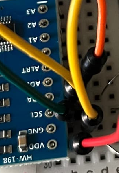
I am desperatly trying to connect an ADS1115 on an ESP32 (WROOM).
I stay put at the I2C scanning step : no device is found.
I am using : the latest esp32 by espressif systems card softwares, and the basic Wire library included. (I tested serveral ADS1115 libraries, but it is not probably the cause.)
I have tried several versions of the software, custom Wire library.
I have also tried to change the usual pins on the ESP32 . (GPIO 21: SDA; GPIO 22 : SCL)
Of course, I have changed boards and ADS1115.
I put pull up resistors, without any additionnal success.
This is really frustrating; it seems like everbody can do it ... except me.
Do you have any clue ? Thanks !
My latest tests are based on this sketch
#include <Wire.h>

void setup() {
  Wire.begin();
  Serial.begin(115200);
  Serial.println("\nI2C Scanner");
    byte error, address;
  int nDevices;
  Serial.println("Scanning...");
  nDevices = 0;
  for(address = 1; address < 127; address++ ) {
    Wire.beginTransmission(address);
    error = Wire.endTransmission();
    if (error == 0) {
      Serial.print("I2C device found at address 0x");
      if (address<16) {
        Serial.print("0");
      }
      Serial.println(address,HEX);
      nDevices++;
    }
    else if (error==4) {
      Serial.print("Unknown error at address 0x");
      if (address<16) {
        Serial.print("0");
      }
      Serial.println(address,HEX);
    }
  }
  if (nDevices == 0) {
    Serial.println("No I2C devices found\n");
  }
  else {
    Serial.println("done\n");
  }
  delay(5000);
  Serial.print("i2c devices found:");
  Serial.println(nDevices);
}

void loop() {

}