ESP8266 / ESP-12F goes into wrong boot mode after deepsleep

Hi there!

So i've been developping and enjoying quite fancy (to me!) battery-powered thermometers. So far there is 9 of these working properly.

Wake-up, get measurements, connect to WiFi, send these into an InfluxDB database, deepSleep. Done between 0,5 and 2,5s on average. 40-ish µA consumption on deepSleep so battery should be fine for a large month if I take values every 2 minutes. I'll reduce measurements' frequency later.

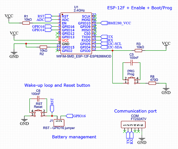
Here is how I wired ESP-12F's:

I wanted to assemble and store remaining PCBs so I bought again some ESP-12F from the same AliExpress buyer.

What could happen, did happen: I got delivered another version, probably a lower quality clone.

Problem is that ESP-12F from my second delivery never wake up to run the sketch again.

So I had a look on boot modes and rst causes.

On power-on, i get an understandable rst cause:1, boot mode:(3,0)
After the deepSleep cycle OR if I hit reset during the deepSleep cycle, I only get ets Jan 8 2013,rst cause:2, boot mode:(3,2) and nothing happens.
After the deepSleep cycle OR If I hit reset button again, I get rst cause:2, boot mode:(3,6) and the thermometer does its work once.

I found online that pulling up to VCC MOSI or MISO pins could solve this problem, but it did not seems to work for me.

==> Does anyone have a lead for me to follow, please?

For me this can not be a sketch problem since I have 9 thermometers working just fine, but if sketch is needed, I'll translate comments and variables into English during the weekend.

Thanks a lot!
Thomas
Check, new board with multimeter, maybe GPIO0 is connected to gnd?

Hello noobmastha,

Thanks for your reply!


With power off, I've been able to properly check these two resistors' measurements between GPIO0 and VCC for R3, and between GPIO0 and GND while pushing on PRG for R8.

I did not find any continuity between GPIO and GND. When checking the opposite (multimeter's COM on GPIO0 and Red touchpin on GND) I found a "diode-like" reading at 743mV. I can not explain this measurement with ESP-12F's internal circuitry.

With power on:

  • VCC is stable at 3.33V at all time.
  • I find a stable 3,3V between GPIO0 and GND and startup.
  • If I press Reset, it drops to 2.5V (!?).
  • If a press Reset again, it rises back at 3,3V (!!).
  • It will flip back and forth at each Reset pressing...

Working thermometers do not behave like this. GPIO0 is at VCC potential and have just a few tens mV drop when pressing Reset, probably beacause I did not add a pull-down resistor between RST and GND when pressing Reset button.

What do you think about this wiring?

Thanks a lot again!
Thomas

Well considering that GPIO 0 is within bounds (not pulled LOW) and GPIO 15 is pulled LOW as it should be, there are 2 more pins we need to check.

  • GPIO 2 looks like it isn't connected, but is there a LED connected to it ? How has that been connected ? a simple active LOW is fine of course, the LED & resistor pull it up, but maybe there is something else going on there. Can you add 10K pullup to the pin ?

  • GPIO 1 (TX) should also not be pulled LOW, and again maybe you can add a pullup there to see if that helps.

Still it is a bit strange, because all that really happens when waking up from deep sleep is that GPIO16 pulls RST LOW, and for the rest the boot procedure is normal.

I found something here where there is a bit more explanation of the second digit in the boot mode. If it is 2 (as in boot mode 3,2) that means that it is 'jumping Boot' i don't know why it does that, instead 3,0 (remapping) , and actually it seems that only the first digit is influenced by the GPIO states.

So i provided you with some more information, which unfortunately i don't think will help you much.

Maybe you should just order so other units from Ali (or a different source) i got some from here and those are fine, though i am not using them with deepsleep, so i can't help you with that or verify that that works as it should.

btw, shouldn't RST have a pullup resistor ?

Hi Deva_Rishi, thanks for your reply!

Pulling-up GPIO1:

1st boot ==> rst cause: 1, boot mode:(3,0) ==> Normal behavior
2nd boot / 1st reset press: rst cause:2, boot mode:(3,2) ==> 'Zombie' mode
3rd boot / 2nd reset press : rst cause:2, boot mode:(3,6) ==> Normal behavior

Pulling-up GPIO2:
This pin is left floating, no LED or whatever is wired.
Very same results as GPIO 1 / TX when I pull-up this pin :cry:

I understand this information as you do. So the goal should be to avoid said "Jump boot mode (3,2)" and have proper "Flash boot mode (3,6)" instead.

Well it most certainly should, but it did not seem obvious to me when I designed this little thing :sweat_smile:
I tried to pull up RST pin, sadly no change noticed.

Fun fact, thermometers that work fine behave as following:
1st boot / powering on: rst cause:1, boot mode:(3,0)
2nd boot and followings / either pressing Reset or waiting for waking up: rst cause:2, boot mode:(3,2)

So boot mode (3,2) does not seem to be the problem itself.

Maybe I should have a look onto the software side? I'm not talking about the sketch, but maybe Arduino IDE's parameters? Flash sizes, ROM mapping, etc..?

In the end of the day, I may buy others units as you suggested. Can you please confirm the via partern you have, as I showed in the first post? There is obviously a design difference that I should avoid.

But there is a LED on the unit, and it is wired active LOW to GPIO 2 (or at least there is on mine)

Possibly, what have you selected now ? It should be a 4MB flash size.

Yes it is similar, one long row of vias all the way along between the cover and the antenna.

@Deva_Rishi Sorry for late reply, Christmas time is a rush! :sweat_smile:

Here are parameters I use to get first ESP-12F working properly.
cqCnmFPxxm

Following your advice, I also tried with 4MB flash size. I also tried with and without erasing the full sketch. Sadly, no

I'm going to purchase a bunch from Estardyn to give them a try and I messaged the first vendor (Diymore PCB Store).

That's quite frustrating, i'm pretty sure there is a simple trick to make it work properly! :face_with_raised_eyebrow:

@tornix, did you have more luck with the new batch? I'm have 3 for 3 from TZT and one from Electronic Kit Store that consistently turn zombie after deepsleep. I'm testing with diode between WAKE and RST, and (extra) Pull-Up on GPIO0 and GPIO2 as mentioned in The black magic of returning from Deep Sleep every time - Everything ESP8266

Hi @jshansen, it drives me crazy since there is no consistency even with big sellers as you mention.

Here is my ESP-12F purchase history:

  • 2022/11/28 ; 10 pcs from Diymore PCB Store ==> Working great
  • 2023/11/26 ; 10 pcs from Diymore PCB Store ==> Zombie mode
  • 2023/12/28 ; 4 pcs from Estardyn Official Store ==> Working great
  • 2024/01/16 ; 5 pcs from Estardyn Official Store ==> Zombie mode*

*This last batch went into Zombie Mode, then I found an unusual piece of code written for D1 mini clone that may have a similar issue. It made deepsleep work properly... for a few days. Then my ESP-12F went into instant reboot, as you can see on the battery voltage monitoring.

Here is the mentioned code:

#include "ESP8266WiFi.h"
extern "C" {
#include <user_interface.h>
}

#define ets_wdt_disable ((void (*)(void))0x400030f0)
#define ets_delay_us ((void (*)(int))0x40002ecc)

#define _R (uint32_t *)0x60000700


void nk_deep_sleep(uint64_t time)
{
    ets_wdt_disable();
    *(_R + 4) = 0;
    *(_R + 17) = 4;
    *(_R + 1) = *(_R + 7) + 5;
    *(_R + 6) = 8;
    *(_R + 2) = 1 << 20;
    ets_delay_us(10);
    *(_R + 39) = 0x11;
    *(_R + 40) = 3;
    *(_R) &= 0xFCF;
    *(_R + 1) = *(_R + 7) + (45*(time >> 8));
    *(_R + 16) = 0x7F;
    *(_R + 2) = 1 << 20;
    __asm volatile ("waiti 0");
}

void setup()
{
    delay(1000);
    Serial.begin(74880);
    Serial.println("setup");
    delay(5);
    nk_deep_sleep(120E6);
    Serial.println("never reached");
    delay(5);
}

void loop()
{
}

Let's be honnest, I don't understand this code at all. But it worked for a while, then something happened and now my device goes crazy and restart without really deepsleeping.

No further investigation on my side so far.

Here are sources. It may be hardware related, as your link also mentions. There may be something wrong about the reset signal waveform.

It seems this is not a solved issue so far.

I wanted to buy genuine Espressif modules, but I couldn't find a seller, so yesterday I bought 5 ESP-12F from Az-Delivery, their Amazon store.

Even if each module is going to cost from 2 to 3 times the AliExpress cost, they are known for their quality.
My guess is (hope also) it may be more cost efficient to buy expensive working modules than hoping that clones will do their work properly.

1 Like

I am not saying i fully do, but it seems that

#define ets_wdt_disable ((void (*)(void))0x400030f0)
#define ets_delay_us ((void (*)(int))0x40002ecc)

#define _R (uint32_t *)0x60000700

The first two macros are pointing to a point in the SDK from where the functions are executed (this probably depends on which SDK function is on ESP-chip

The third points to an address in (flash or RAM ?) memory and in the function where it is referenced, values are assigned to addresses relative to that base address.

ESP8266 chips come from Espressif without a flash chip. A board vendor can add a flash chip to it and as a result there is a rather big variance in the types of flash chips used, mainly in size, but also in some other details.

That is the issue. Espressif doesn't sell modules which include a flash chip. They sell only the processor.

Thank you for the thorough response. We're on the same page and the quality of these modules are possibly fighting the tight tolerances which leads to the variability. But it's just not good enough. I'm looking at adafruit which has a full board and even at 5-7x the price, it starts to look like the right choice to go with a vendor with reputation and something on the line.

The really fun part is that while the WAKE-RST connection is described as required, it isn't what's waking up these chips now. They awake with or without that connection, then stumble into one or the other dead end.