certainly can be a problem - have simplified code to use DE and RE both linked to pin 7
// RS485 using ESP8266 SoftwareSerial pin D5 Rx and pin D6 Tx
// set Tools/Board NodeMCU 1.0 (ESP-12 Module)
// load EspSoftwareSerial from https://docs.arduino.cc/libraries/espsoftwareserial/
#include <SoftwareSerial.h>
// RS485 VCC ESP8266 to to 3.3V
// ESP8266 pin Rx GPIO14 (D5) to RS485 RO
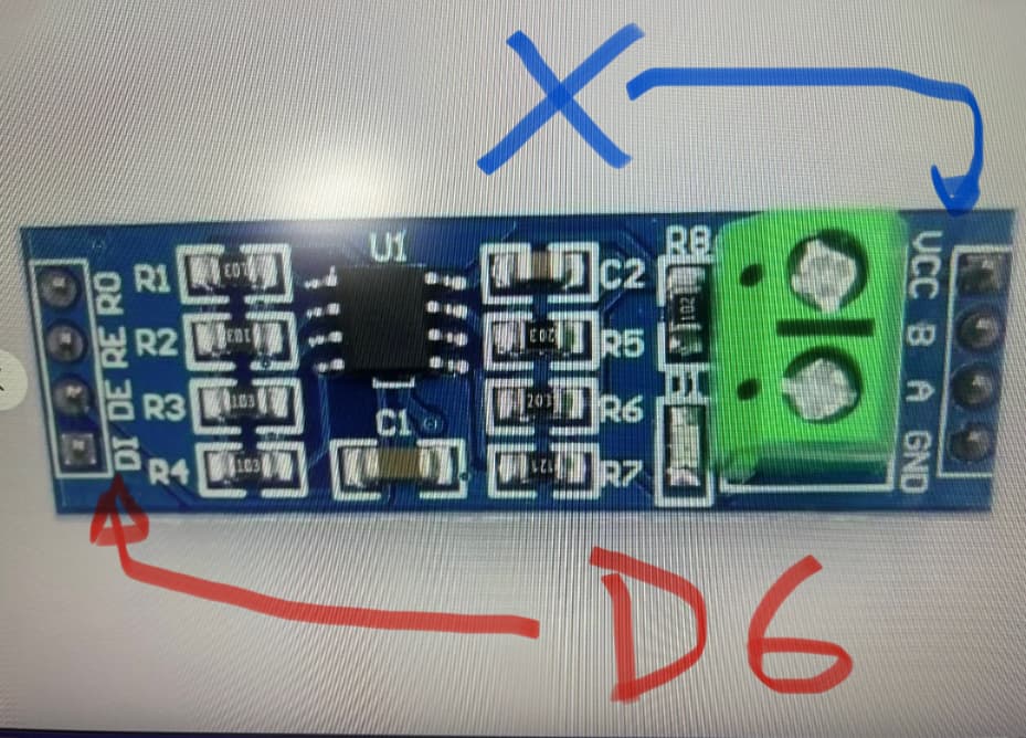
// ESP8266 pin x GPIO12 (D6) to RS485 DI
SoftwareSerial RS485Serial(D5, D6); //14, 12);
// RS485 DE and RE to ESP32 pin 7
#define DE_RE D7 //RS485 Direction control DE and RE jumpered together
#define RS485Transmit HIGH
#define RS485Receive LOW
void setup() {
while (!Serial)
;
delay(1000);
// Start the built-in serial port, probably to Serial Monitor
Serial.begin(115200);
Serial.println("\n\nESP8266 to RS485 - Use Serial Monitor, type in upper window, ENTER");
pinMode(DE_RE, OUTPUT);
digitalWrite(DE_RE, RS485Receive); // Disable RS485 Transmit
RS485Serial.begin(9600); //Initialize software serial with baudrate of 115200
}
// loop sending data from Mega to RS485 and receiving data
void loop() {
// read characaters from Serial Monitor transmit over RS485
if (Serial.available()) { // Arduino Serial data avaliable?
digitalWrite(DE_RE, RS485Transmit); // Enable RS485 Transmit
RS485Serial.write(Serial.read()); // Send byte to Remote Arduino
RS485Serial.flush(); // wait for byte to be transmitted
digitalWrite(DE_RE, RS485Receive); // Disable RS485 Transmit
}
// read characaters from RS485 display on serial monitor
if (RS485Serial.available()) // RS485 serial data available?
Serial.write(RS485Serial.read()); // read character and display it
}
Nano code
// Arduino Uno/Nano RS485 using AltSoftSerial

#include <AltSoftSerial.h>
#define SSerialTxControl 3  //RS485 Direction control DE & RE jumpered together

#define RS485Transmit HIGH
#define RS485Receive LOW

// use AlTSoftSerial from https://www.pjrc.com/teensy/td_libs_AltSoftSerial.html
AltSoftSerial RS485Serial;  // RX on pin 8, TX on pin 9

void setup()
{
  while (!Serial)
    ;
  delay(1000);
  Serial.begin(115200);
  Serial.println("\n\nNano to RS485 - Use Serial Monitor, type in upper window, ENTER");
  Serial.println("Use Serial Monitor, type in upper window, ENTER");
  pinMode(SSerialTxControl, OUTPUT);
  digitalWrite(SSerialTxControl, RS485Receive);  // Init Transceiver
  RS485Serial.begin(9600);  // set the RS485 data rate
}

void loop() {
  if (Serial.available()) {
    char byteReceived = Serial.read();
    digitalWrite(SSerialTxControl, RS485Transmit);  // Enable RS485 Transmit
    RS485Serial.write(byteReceived);                // Send byte to Remote Arduino
    RS485Serial.flush();
    digitalWrite(SSerialTxControl, RS485Receive);  // Disable RS485 Transmit
  }
  if (RS485Serial.available())  //Look for data from, RS485
  {
    char byteReceived = RS485Serial.read();  // Read received byte
    Serial.write(byteReceived);              // Show on Serial Monitor
  }
}
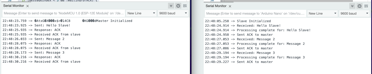
ESP8266 serial monitor output
ESP8266 to RS485 - Use Serial Monitor, type in upper window, ENTER
hello from nano
test2 from nano 1234567890
test3 from nano abcdefghijklmnopqrstuvwxyz
nano serial monitor output
Nano to RS485 - Use Serial Monitor, type in upper window, ENTER
Use Serial Monitor, type in upper window, ENTER
hello from ESP8266
test2 from esp8266 0987654321
test3 from esp8266 ahatsvgmjkdoierm fdocvuyhnmerdloxdjeswlwemjksjnhjmxzkjsxj
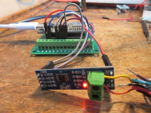
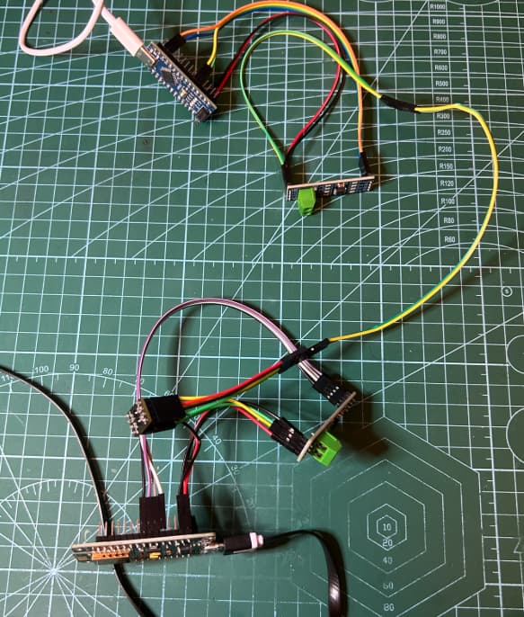
photo