Hello everyone.
I decided to write here about my problem when it comes to DFPlayer. In general, I have a code that turns the LED on and off. there is also a flashing LED as turn signals and emergency. And i also decided to put a DFPlayer that will play me the sound of the car engine (1:24 scale toy). there are some tutorials on how to run the dfplayer without arduino and i decided to use it in my place as i am very bad at coding. and i thought that if i connect the power pin from dfplayer to pin D2 and when i switch the motor on the button will start the sound. unfortunately it turned out that instead of sound i have some distortion.... of course it's probably the power supply which is too low for this purpose. so it remains for me to connect the power supply before the stabilizer (ams1117 as in picture 2) and control it with the rx and tx pins.... unfortunately i don't know how to do this so i thought maybe someone here has more knowledge about this than me and will be able to help me.
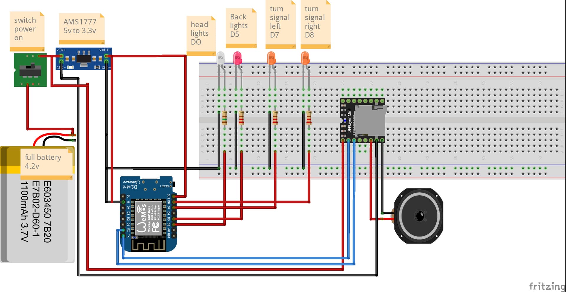
1 picture shows how I did it
2 picture shows how I will probably have to do it but the problem is the code I can't write to my already existing one
because there you probably need to use commands like “serialprints” and the library “DFRobotDFPlayerMini” or something similar.
I have seen different codes on the internet but they looked very elaborate to handle mp3 player or triggered from a button... but in my case it is a bit different....
also gives my code that I have for controlling leds and DFPlayer with D2 pin as power (which of course does not work because there is no power)
Put two of those 3.7v batteries in series then the AMS1777 can do it's job. I am referring to picture 1. Picture 2 needs another BUCK converter from 7ish to 5V.
and one battery won't work if I connect the dfplayer module before the stabilizer?
because I once connected the module to the battery and it started
I think that if I connected the module even behind the stabilizer like esp8266 it would work .. but the problem is with coding and how to write the code to control the module via rx/tx.
I saw something similar on one page but there was no code there. only an image and you can't see the power connection to dfplayer:
Edit:
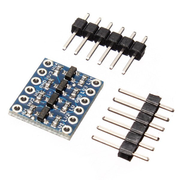
I also saw something like a logic level converter.. but does something like that increase the voltage on the pin? (of course this is one of the solutions if it worked) and if not then I can use an old mp3 player and start the sound from it.. only downside of this is that the song plays in the place when the power is turned off (i.e. not from the beginning)
TLDR. That battery is a 3.7V battery, the only time it is 4.2V is when it is attached to a charger. The 5V to 3.3V VR needs about 6V to operate but you don't even have 5V. You will need 2 Voltage regulators, each is attached to the two 3.7V batteries in series, one outputs 3.3V the other 5V. The level shifter is not the solution, it needs both 3.3V and 5V. You can't get rid of one Voltage with it.
in this diagram as an example I connected the module and esp8266 at the same time and it works with a battery from an old phone
so why shouldn't it work?
power supply from pin d2 is not possible because it has 3.3v
so I guess I have to do it like that and control dfp via pins rx/tx
am I right or not?
Sorry, I don't understand what your problem is. In your first post all you need to do is place 2 3.7V batteries in series, and add a buck converter to convert the 7ish V to 5V to power the 5 V devices.
You do understand that 3.7V is too low for a 5V to 3.3V VR? It's basic arithmetic, 3.7 is LESS than 5. What you need is a BOOST converter. It must be a type that allows the full usable range of voltages the battery will deliver
You can fit two lower capacity batteries in place of that one.
Until you understand the rules re power to each device and how to convert from one voltage to another, you will make no headway.
hmm..
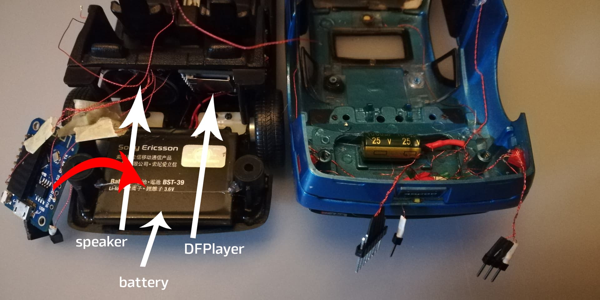
tomorrow I'll try something else.. I'll try an old mp3 player (as I showed in the picture above)
connect it with esp8266. so minus to esp and plus will be from pin D2.. and then when I turn on the button on the phone then the current should flow to the mp3 and play the sound.
I didn't feel like waiting until tomorrow and connected the mp3 hardener as + to D2 and minus as ground.
and unfortunately after turning on the button on the phone all I could hear was some beeping in the headphones and the diode on the player module flashed a few times and that was it.. it looks like nothing will come of it... so I guess the car will be without sound.
a bit of a shame but what can you do...
Hmm.
I found a topic and it turns out that something similar works with one 3.7v battery..
it is true that it is a slightly different module but the principle of operation is probably the same.
of course, on the website in its diagram there is no voltage regulator and everything is connected to 5v.
but despite that it probably works for him.. and that is why I also wanted to get something like that since I cannot get such voltage on pin D2 to start dfplayer.
so I would have to pull the voltage directly to the module and control it via pin Tx and Tx